Three-rod module attitude coutrol mechanism test method

A technology of attitude control and testing methods, applied in general control systems, control/adjustment systems, test/monitoring control systems, etc.

Inactive Publication Date: 2006-10-25
NANJING INST OF ASTRONOMICAL OPTICS & TECH NAT ASTRONOMICAL OBSE
View PDF1 Cites 10 Cited by
  • Summary
  • Abstract
  • Description
  • Claims
  • Application Information

AI Technical Summary

Problems solved by technology

And there is no ready-made technolo

Method used


Image

  • Three-rod module attitude coutrol mechanism test method
  • Three-rod module attitude coutrol mechanism test method
  • Three-rod module attitude coutrol mechanism test method

Examples


Embodiment 1

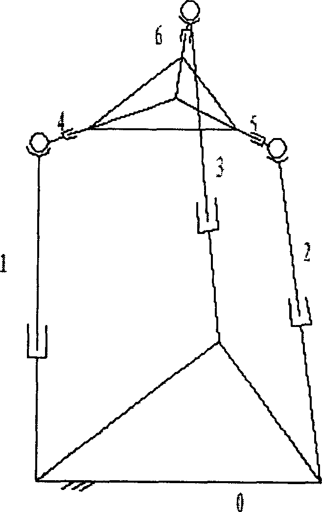
[0045] Example 1, in the pre-research of the active main reflector of the large radio telescope "FAST" in my country, the test of the "three-rod module attitude control mechanism" used to control the movement of the active reflector unit block.

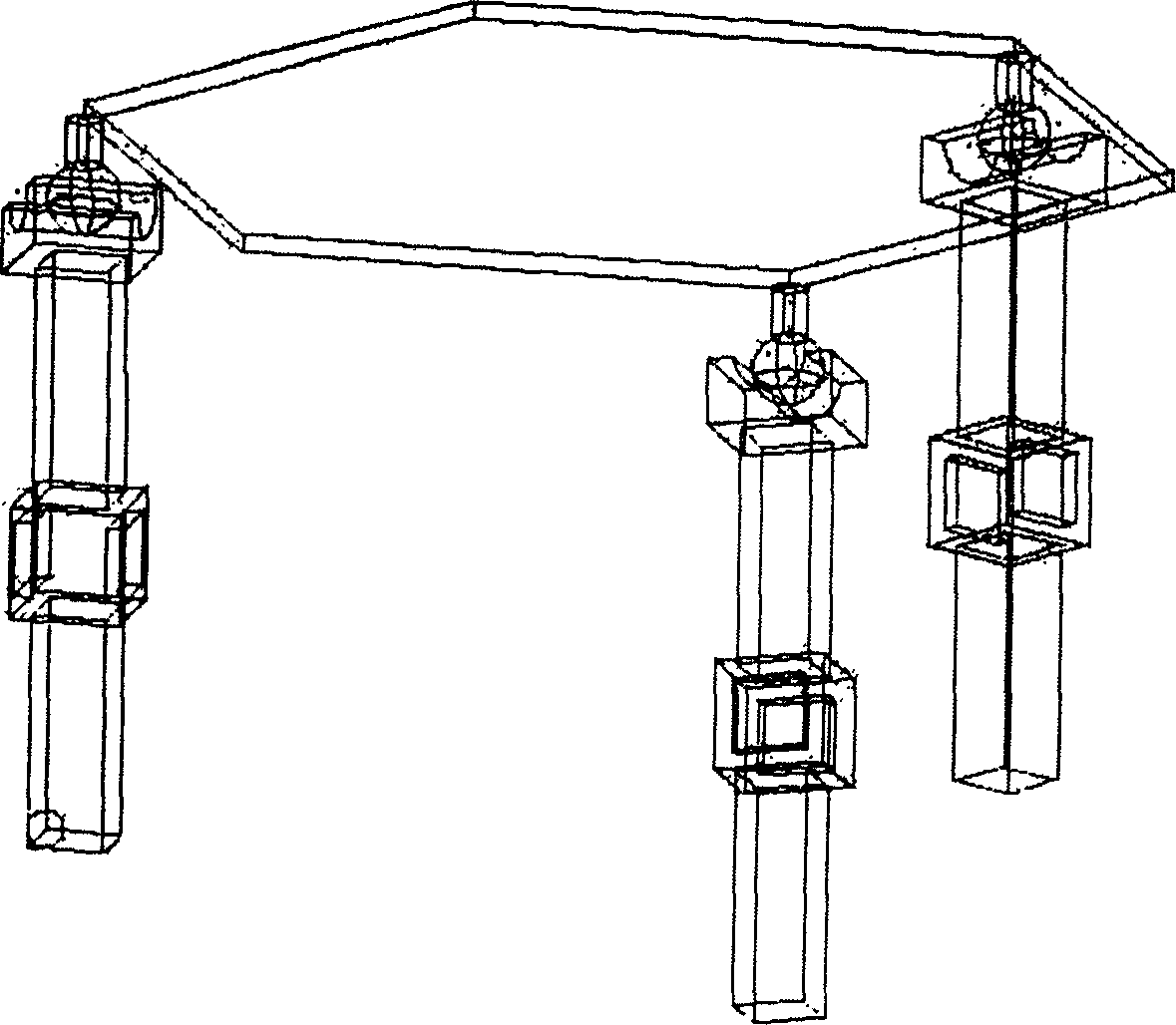
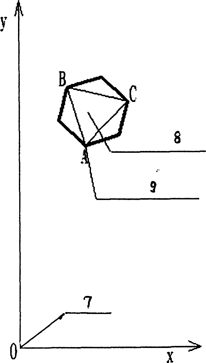
[0046] refer to figure 2 , image 3 : The installation and measurement of the experimental device of the three-bar module attitude control mechanism are completed with the help of a total station. First, the total station is placed on the fixed base at position 7 in the figure, and a target is pasted on a pillar about 42m away to establish a coordinate system. For the position of unit block 8 in the coordinate system see image 3 , 9 represents the measured point. Before each measurement, the target was re-measured with a total station to determine the initial position. Three main items are measured. The first is the positioning accuracy of the actuator; the second is the repositionability of the back frame and the actuator itse...


PUM


Abstract

Said method contains first setting electronic tachometer establish on one fixed baseplate and sticking target on post at specific intervals, before each measurement utilizing electronic tachometer to proceed once retest for determining initial position, sticking more than three targets on tested unit block and configuring in coordinate system, then respectively measuring following three items: actuator setting accuracy, papoose carrier and actuator reset quality after actuator up and down movement, papoose carrier and not lifting position relative amount of amount of turning after three actuator simultaneously rising certain of distance. The present invented method is simple and utility, solving testing and debugging technical matters for active optics astronomical telescope or radiotelescope neutron reflecting mirror module attitude control mechanism with active principal reflection surface.

Description

technical field [0001] The invention relates to a testing method of an instrument, in particular to a testing method of a three-bar module attitude control mechanism. Background technique [0002] The larger the aperture of the astronomical telescope, the more celestial body information can be obtained. Therefore, building a huge astronomical telescope has always been the goal pursued by astronomers. However, as the aperture of the telescope increases, the difficulty of construction will increase exponentially. so that it cannot be built. The prior art uses splicing large-scale telescope technology to solve this contradiction, that is, a large-scale astronomical telescope is spliced ​​by several "sub-mirrors"; each sub-mirror in the splicing structure moves simultaneously under the control of the control system, which can form the deformation of the entire mirror surface , to meet the needs of astronomical observation, this technology is applied to the astronomical telescop...

Claims


Application Information

Patent Timeline
IPC IPC(8): G05B23/00
Inventor 陈忆屈元根
Owner NANJING INST OF ASTRONOMICAL OPTICS & TECH NAT ASTRONOMICAL OBSE
Why Eureka
Try Eureka