Pulling device of sewing machine

A technology for sewing machines and objects to be sewn, applied to sewing machine components, sewing equipment, lubrication/cooling devices, etc., can solve problems such as heat generation and wear, achieve low frictional resistance, reduce load, and improve durability

Active Publication Date: 2006-11-01
JUKI CORP
View PDF1 Cites 2 Cited by
  • Summary
  • Abstract
  • Description
  • Claims
  • Application Information

AI Technical Summary

Problems solved by technology

Therefore, when the high-speed operation is stopped or the like, the thrust plate and the clutch spacer slide on the contact surface, and heat may be generated on the contact surface on the clutch sleeve side m...

Method used


Image

  • Pulling device of sewing machine
  • Pulling device of sewing machine
  • Pulling device of sewing machine

Examples


Embodiment Construction

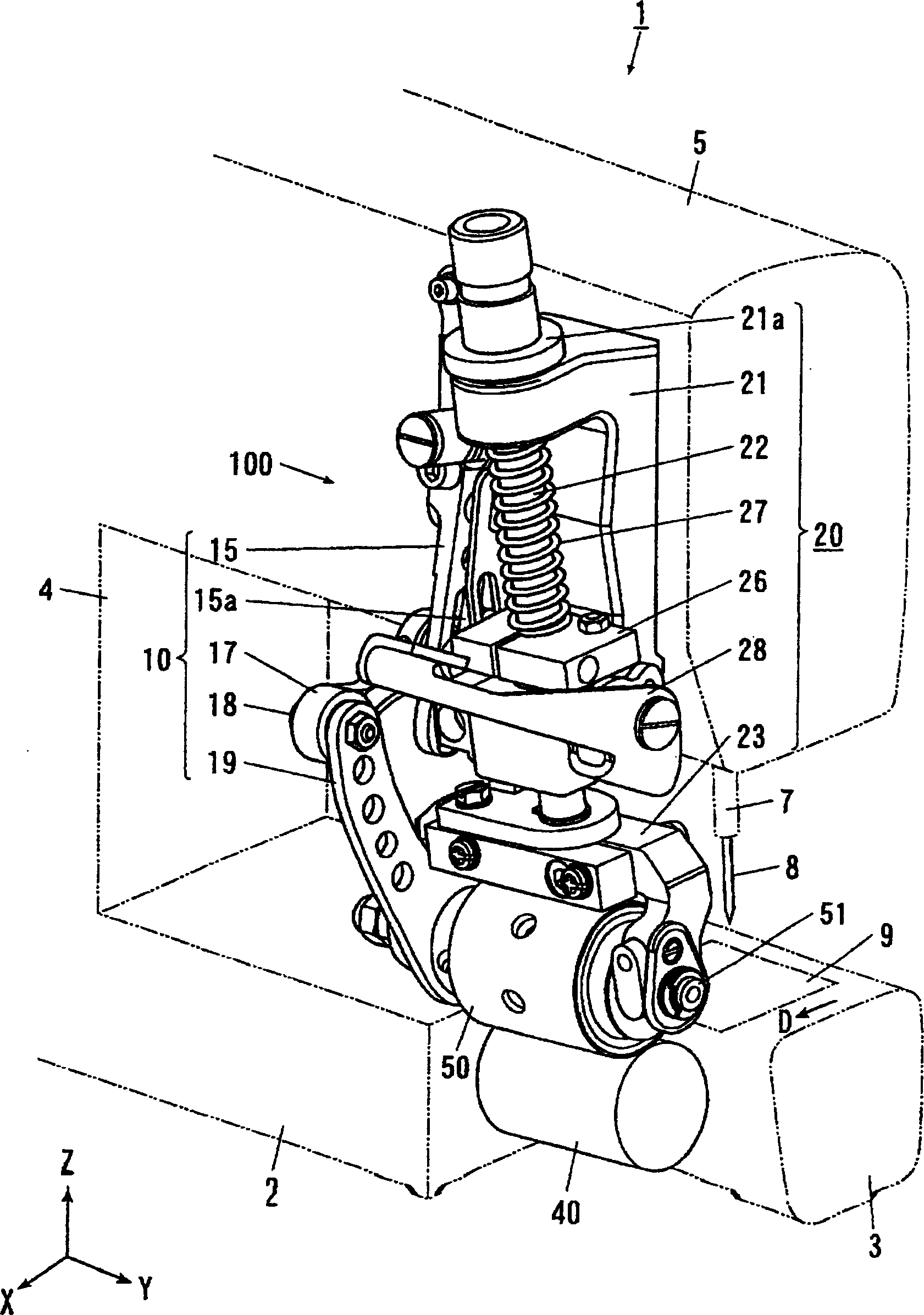
[0069] Below, based on Figure 1 to Figure 5 Embodiments of the present invention will be described in detail. In this embodiment, the pulling device 100 of the sewing machine is provided as the conveying mechanism, which applies a pulling force toward the downstream side in the conveying direction to the cloth on the downstream side of the sewing position in the conveying direction. Furthermore, in this embodiment, the direction in which the needle 8 moves up and down is referred to as the Z-axis direction (up-and-down direction), and one direction perpendicular thereto (the conveying direction of the object to be sewn) is referred to as the X-axis direction (front-rear direction). , the direction perpendicular to both the X-axis direction and the Z-axis direction will be described as the Y-axis direction (left-right direction). In addition, in this embodiment, the cloth which is a to-be-sewn object is conveyed in the X-axis direction, that is, figure 1 In the direction of ...


PUM


Abstract

The invention provides a pulling device of a sewing machine, which can make the sewing machine run stably at high speed. In the pulling device (100) with the clutch sleeve (53a, 53b) and the spacer (54) of the built-in one-way overrunning clutch, on the opposite end faces of the clutch sleeve (53a) and the spacer (54), respectively Two first thrust plates (56a, 56b) made of phosphor bronze are provided, and one second thrust plate (57) made of steel is provided between the two first thrust plates. Each first thrust plate is respectively engaged with the opposite end surfaces of the clutch sleeve (53a) and the spacer member, and can rotate integrally with them in the direction around the axis. In addition, an oil supply path (55) is formed on the clutch sleeve (53a), and through holes are formed on each of the first thrust plate and the second thrust plate. Guide grooves (A, B, C) for guiding grease are provided on the end surface of the second thrust plate, and grease can be supplied from the oil supply path.

Description

technical field [0001] The invention relates to a pulling device for a sewing machine. Background technique [0002] In the pulling device of the sewing machine that applies a pulling force toward the downstream side of the cloth feeding direction to the sewn object such as cloth, the upper and lower sides of the sewing position in the cloth feeding direction, that is, the downstream side of the needle drop position are arranged to face each other up and down. At least one of the roller and the lower roller rotates as a drive wheel, so that the cloth held between the gap between the two is sequentially conveyed to the downstream side. Also, a known pulling device of a sewing machine is equipped with an upper roller incorporating a clutch mechanism that converts the swing motion of the arm obtained from the main shaft rotated by the sewing machine motor via a cam mechanism or a link mechanism into one direction. intermittent rotary motion (for example, refer to Patent Docume...

Claims


Application Information

Patent Timeline
IPC IPC(8): D05B27/10D05B71/00
Inventor 河本修石川孝则
Owner JUKI CORP
Why Eureka
Try Eureka