Electromagnetic driver of sewing machine

An electromagnetic drive, sewing machine technology, applied in sewing machine components, sewing equipment, cloth pressing mechanisms, etc., can solve the problems of insufficient magnetic force, difficult and inconvenient pressing feet of sewing machines, etc. cost effect

Active Publication Date: 2011-08-17
SHING RAY SEWING MACHINE
View PDF7 Cites 0 Cited by
  • Summary
  • Abstract
  • Description
  • Claims
  • Application Information

AI Technical Summary

Problems solved by technology

However, with such a design, although the elastic element in the linkage device does not need to continuously resist the gravity of the movable iron core 140 during sewing, thereby prolonging the service life of the elastic element, the compression spring 160 itself will still face elastic fatigue. problem and must be replaced
In addition, because the compression spring 160 is added, when the movable iron core 140 is moved towards the metal base 110 by the magnetic force, obviously the part of the magnetic force will be offset by the elastic force of the compression spring 160, so that the magnetic force will be insufficient. problem, and the problem that the presser foot of the sewing machine is not easy to be lifted occurs again
[0007] This shows that the above-mentioned existing sewing machine electromagnetic drive device obviously still has inconvenience and defects in structure and use, and needs to be further improved urgently.
In order to solve the problems existing in the electromagnetic drive device of sewing machines, relevant manufacturers have tried their best to find a solution, but no suitable design has been developed for a long time, and there is no suitable structure for general products to solve the above problems. This is obviously a problem that relevant industry players are eager to solve

Method used


Image

  • Electromagnetic driver of sewing machine
  • Electromagnetic driver of sewing machine
  • Electromagnetic driver of sewing machine

Examples


Embodiment Construction

[0028] For further elaborating the technical means and effect that the present invention takes for reaching the intended invention purpose, below in conjunction with accompanying drawing and preferred embodiment, to the electromagnetic drive device of the sewing machine that proposes according to the present invention its specific implementation, structure, feature and effect Its effect is described in detail below.

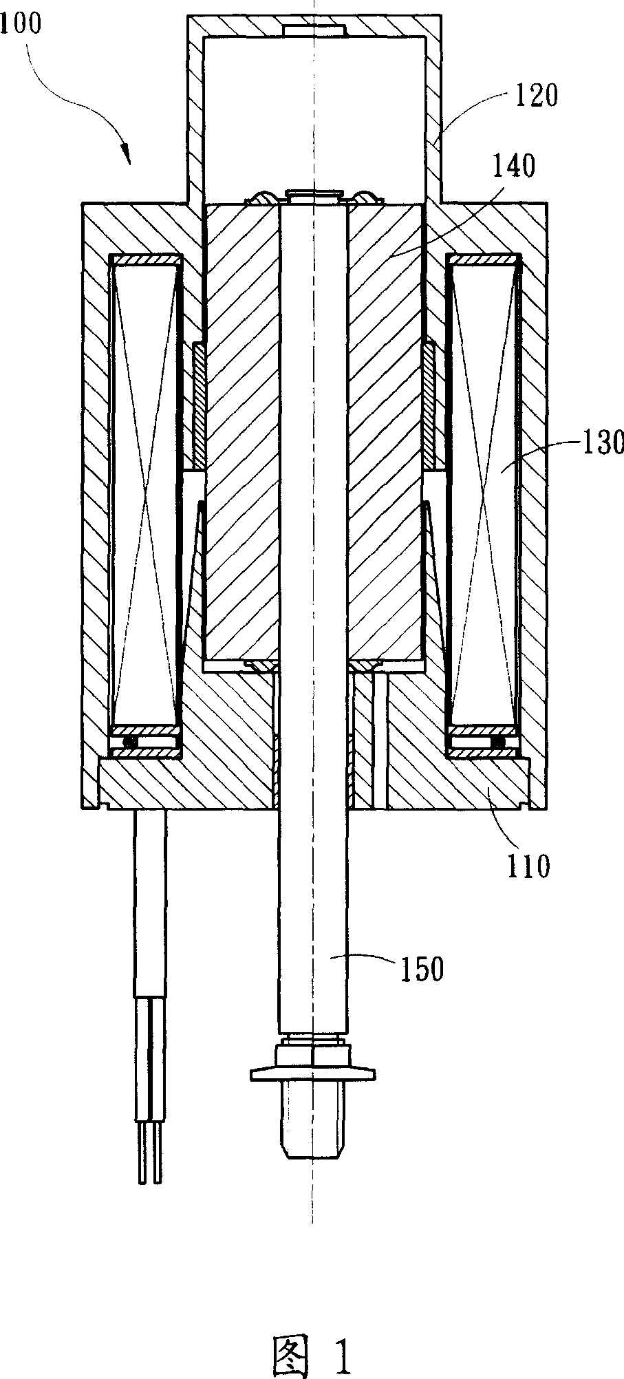
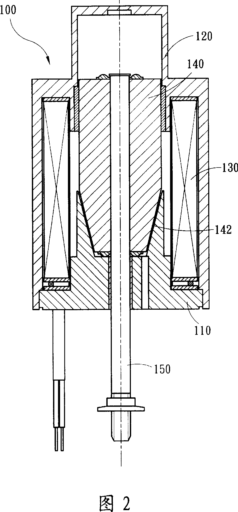
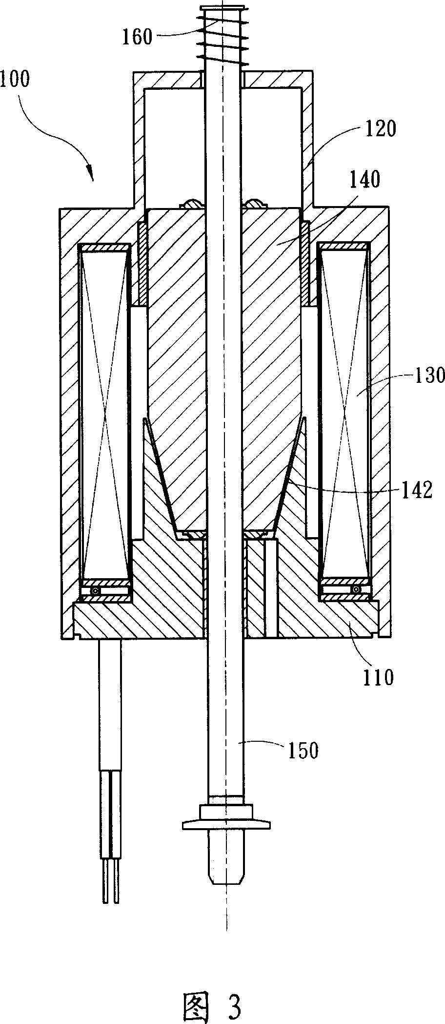
[0029] First, please refer to the Pic 4-1 , Figure 4-2 , Figure 5-1 and Figure 5-2 Shown is the electromagnetic driving device 200 of the sewing machine of the present invention, which is used to drive the action of a presser foot 310 connected to the sewing machine 300. The presser foot 310 is connected by a linkage device 320 and the electromagnetic driving device. 200, and in the present embodiment, the electromagnetic driving device 200 is installed on the outside of the sewing machine 300 in an upright manner, which is mainly composed of a metal base ...


PUM


Abstract

It is a sort of electromagnetic actuating device to drive the walking foot in the stitcher. The walking foot was connected to the actuating device by a linkage. A permanent-magnet was located on movable core. The movable core adsorbs to metal cover via the permanent-magnet at the beginning location so that elastic element in linkage would not have to uphold the movable core all the time. The life-span of the elastic element was prolonged and rubbing and noise were reduced so that the stitcher works more smoothly.

Description

technical field [0001] The present invention relates to an electromagnetic drive device, and in particular to an improved electromagnetic drive device for a sewing machine. Background technique [0002] The presser foot is used to press the cloth in the sewing machine so as to facilitate the sewing operation. When the sewing operation is to be interrupted, the presser foot must be lifted. The mechanism to achieve the actuation of the presser foot is achieved through a linkage device and a drive device, wherein the linkage device is connected between the presser foot and the drive device, and can be driven by the drive device to move the cloth press Lift or press down on the foot. The common driving device in the past is a device of a pneumatic cylinder or a hydraulic cylinder. This driving device is arranged at the bottom of the sewing machine platform and must be connected with the linkage device above the sewing machine platform through a chain. The device has problems s...

Claims


Application Information

Patent Timeline
Patent Type & Authority Patents(China)
IPC IPC(8): D05B29/02
Inventor 卓瑞荣
Owner SHING RAY SEWING MACHINE
Why Eureka
Try Eureka