
Brake apparatus for linear motor and method for positioning movable section of linear motor

A technology of linear motors and moving parts, applied in the direction of electromechanical devices, electric components, automatic brakes, etc., can solve problems such as position deviation

Active Publication Date: 2006-11-01
SMC CORP
View PDF2 Cites 6 Cited by
  • Summary
  • Abstract
  • Description
  • Claims
  • Application Information

AI Technical Summary

Problems solved by technology

Therefore, a problem arises that the movable part, once positioned, may experience a positional deviation due to deformation of the brake pad even after the movable part is positioned relative to the fixed part.

Method used


Image

  • Brake apparatus for linear motor and method for positioning movable section of linear motor
  • Brake apparatus for linear motor and method for positioning movable section of linear motor
  • Brake apparatus for linear motor and method for positioning movable section of linear motor

Examples


Embodiment Construction

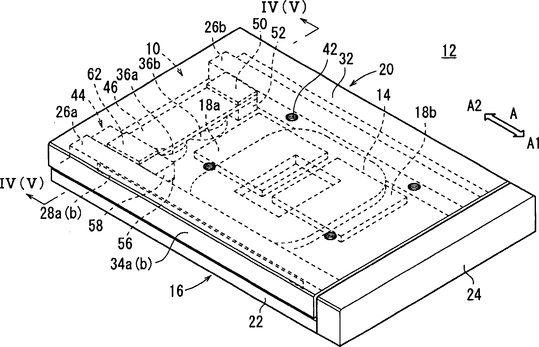
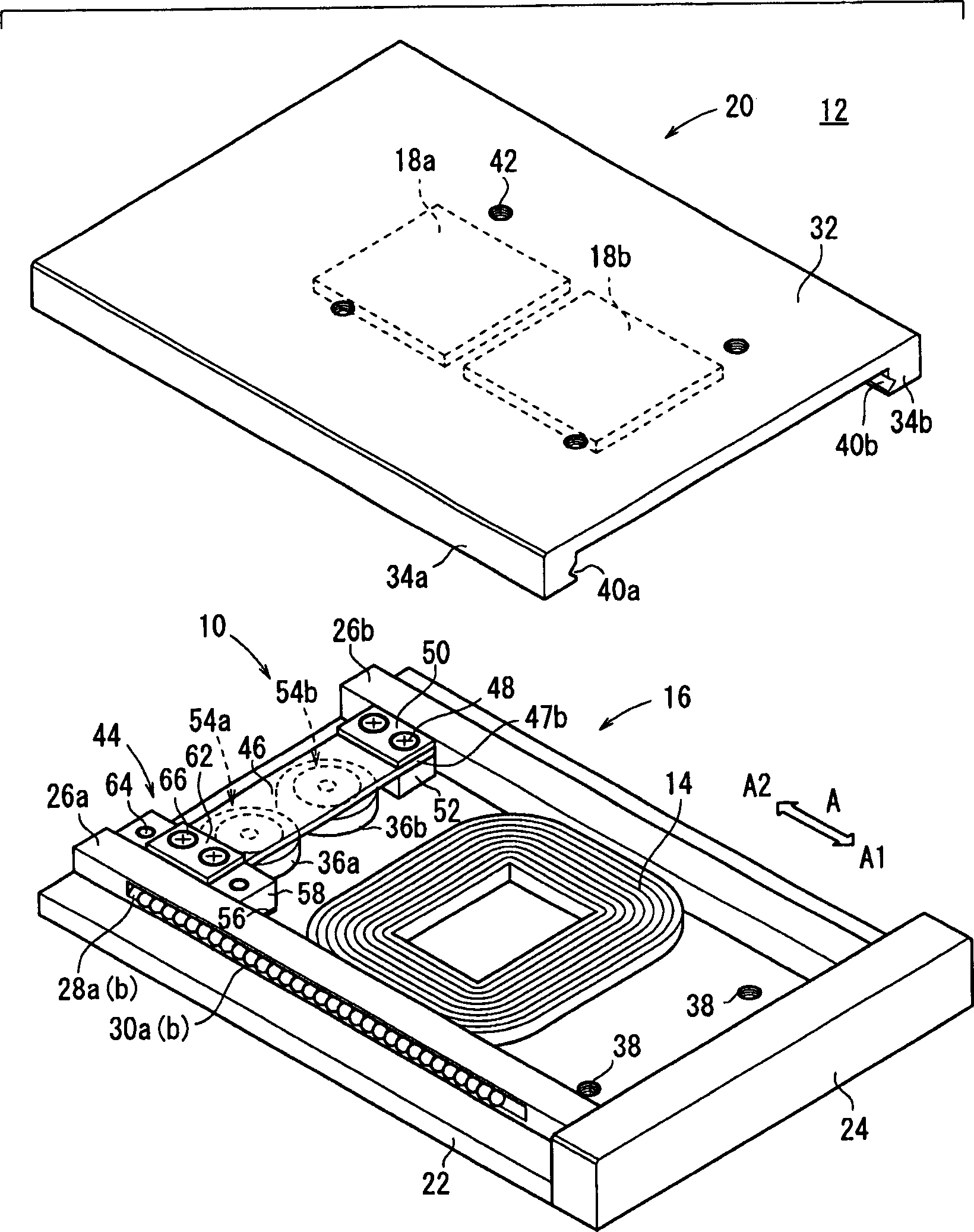
[0015] Such as figure 1 and 2 As shown, a linear motor 12 having a brake device 10 (hereinafter also referred to as "brake device 10") for a linear motor according to an embodiment of the present invention includes a fixed part 16 with a coil 14 and two The movable part 20 of the permanent magnets 18a, 18b arranged opposite the coil 14 .

[0016] Such as Figures 1 to 5 As shown, the fixed member 16 includes a guide rail 22, the coil 14 disposed on an upper surface of the guide rail 22 approximately in the middle, and a drive member 24 including a circuit not shown.

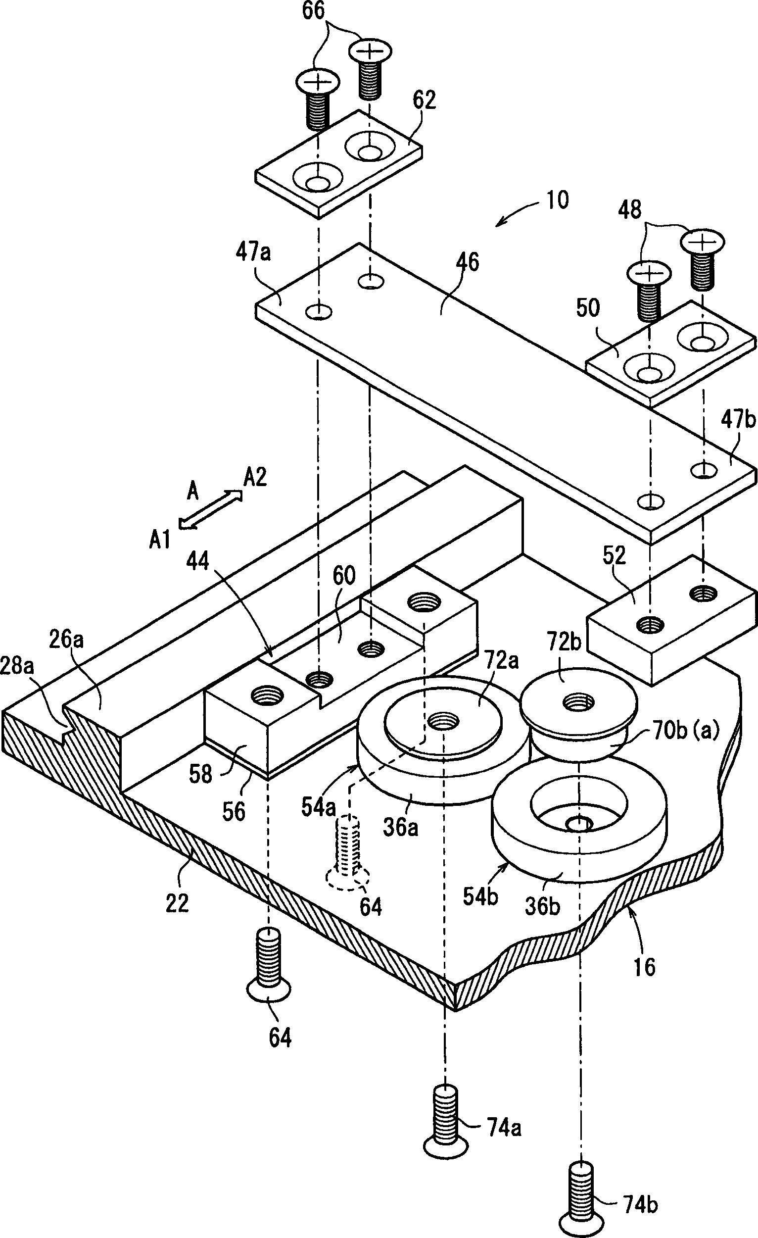
[0017] Protrusions 26 a , 26 b protruding from the bottom toward the movable part 20 are formed on both sides of the guide rail 22 . Such as Figure 1-3 Guide grooves 28a, 28b shown extending in the direction of arrow A are formed on the exterior of the protrusions 26a, 26b, respectively. A plurality of balls 30a, 30b serving as rotating elements are arranged in the guide grooves 28a, 28b. In this arrangeme...


PUM


Abstract

When respective magnetic fluxes are generated by coils and pass through a plate spring, an electromagnetic force, which results from the magnetic flux, is generated within a plate spring, screws, and a magnetic flux-passing member. Therefore, a brake pad is separated from a slide table in accordance with an action of the electromagnetic force exerted against a resilient force of the plate spring. On the other hand, when generation of respective magnetic fluxes from the coils is halted, the electromagnetic force is extinguished, and thus the brake pad presses against the slide table, in accordance with an action of the resilient force of the plate spring.

Description

technical field [0001] The invention relates to a braking device for a linear motor for setting the position of a movable part of the linear motor relative to a fixed part of the linear motor, and to a device for setting the position of the movable part Methods. Background technique [0002] The linear motor includes a coil provided on either one of its movable part and fixed part, and a permanent magnet is provided on the other of the movable part and the fixed part as needed so that the permanent magnet is opposed to the coil. The movable part moves relative to the fixed part by means of a thrust, which is generated based on Fleming's left-hand rule when current flows through the coil. In this arrangement, braking means are arranged to act on the movable part. When the power supplied to the coil is interrupted, or when the movable part moves to a predetermined position, the movable part is set at a predetermined position relative to the fixed part by actuating the brake ...

Claims


Application Information

Patent Timeline
Patent Type & Authority Applications(China)
IPC IPC(8): F16D63/00F16D65/18F16C29/06F16D65/28H02K7/102H02K41/02
CPCH02K7/1026H02K41/03F16D63/00F16D59/02
Inventor 矢岛久志藤原伸广
Owner SMC CORP
Features
  • Generate Ideas
  • Intellectual Property
  • Life Sciences
  • Materials
  • Tech Scout
  • Unparalleled Data Quality
  • Higher Quality Content
  • 60% Fewer Hallucinations
Learn More