Crosslinked air-ducting structure of indoor unit of air conditioner

A technology of air-conditioning indoor unit and air guide structure, which is applied in the direction of air flow control components, etc., which can solve the problems of inconvenient installation of indoor units, narrow air supply range, complex structure, etc., and achieve the effects of reducing the number of layouts, saving costs, and reducing noise

Active Publication Date: 2006-11-01
HAIER GRP CORP +1
View PDF0 Cites 11 Cited by
  • Summary
  • Abstract
  • Description
  • Claims
  • Application Information

AI Technical Summary

Problems solved by technology

But the result is that when the two groups send air to both sides at the same time, the total air supply range of the air conditioner does not expand at this time, but forms a blind area of ​​air supply in the middle; The air range is only concentrated in the middle, not only the air supply range is narrow, but also the air supply in the middle is too concentrated, which will make people feel uncomfortable
Moreover, two sets of blades need to be controlled by two motors, which also leads to a complex structure, which brings inconvenience to the installation of indoor units that originally have little space.

Method used


Image

  • Crosslinked air-ducting structure of indoor unit of air conditioner
  • Crosslinked air-ducting structure of indoor unit of air conditioner
  • Crosslinked air-ducting structure of indoor unit of air conditioner

Examples


Embodiment Construction

[0016] The present invention will be described in detail below through specific embodiments and accompanying drawings.

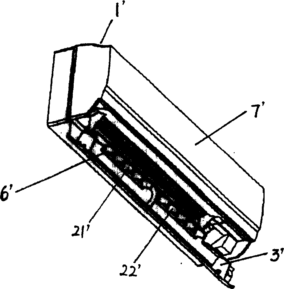
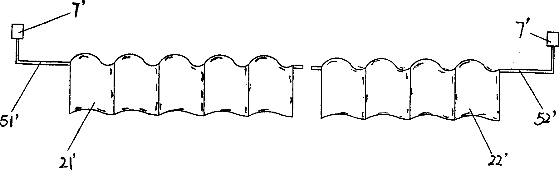
[0017] First of all, it needs to be emphasized that the air-conditioning indoor unit mentioned in the present invention mainly refers to the wall-mounted unit, not including the cabinet structure, because the length of the air outlet of the wall-mounted unit is much longer than the width of the air outlet, which is a long and narrow shape Therefore, people usually design the left and right two parts of the wind guide vane, the specific structure is as follows:

[0018] Such as figure 1 , figure 2 Shown is the structure of the existing air-conditioning indoor unit. Since the existing wall-mounted indoor unit is installed on the indoor wall, its volume cannot be made too large. Usually, the upper part of the indoor unit is provided with an air inlet 1'. A cross-flow fan and an evaporator are installed inside, and an air outlet 6' is installed at the lower p...


PUM


Abstract

The invention relates to a connecting-rod air-guide structure for the room unit of air conditioners, in which air-guide blades are connected by a connecting rod and controlled by a motor. When exhausting the air at the air outlet, the motor drives an air-guide rod to be in the reciprocating motion via the inventive connecting-rod air-guide structure, so as to drive the air-guide blades to be in the side-to-side movement for scavenging.

Description

technical field [0001] The invention relates to an air guiding structure of an indoor unit of an air conditioner, in particular to a connecting rod type air guiding structure of an indoor unit of an air conditioner. Background technique [0002] Air conditioner is indispensable a kind of household electrical appliance in people's daily life. In terms of large systems, air conditioning systems can be divided into refrigeration systems and air circulation systems. The working principle of the air-conditioning system is that the compressor of the refrigeration system compresses the refrigerant to form a high-temperature and high-pressure refrigerant. At this time, the refrigerant is in a gaseous state, and after being cooled by the condenser to a high-pressure liquid state, the volume expands rapidly in the evaporator of the indoor unit. , and re-evaporate into a gaseous state. During this process, the refrigerant has to absorb a large amount of external heat to generate a low...

Claims


Application Information

Patent Timeline
Patent Type & Authority Applications(China)
IPC IPC(8): F24F13/15
Inventor 付裕王勇梁晓东王召兴谷东照管丽萍于兆志
Owner HAIER GRP CORP
Why Eureka
Try Eureka