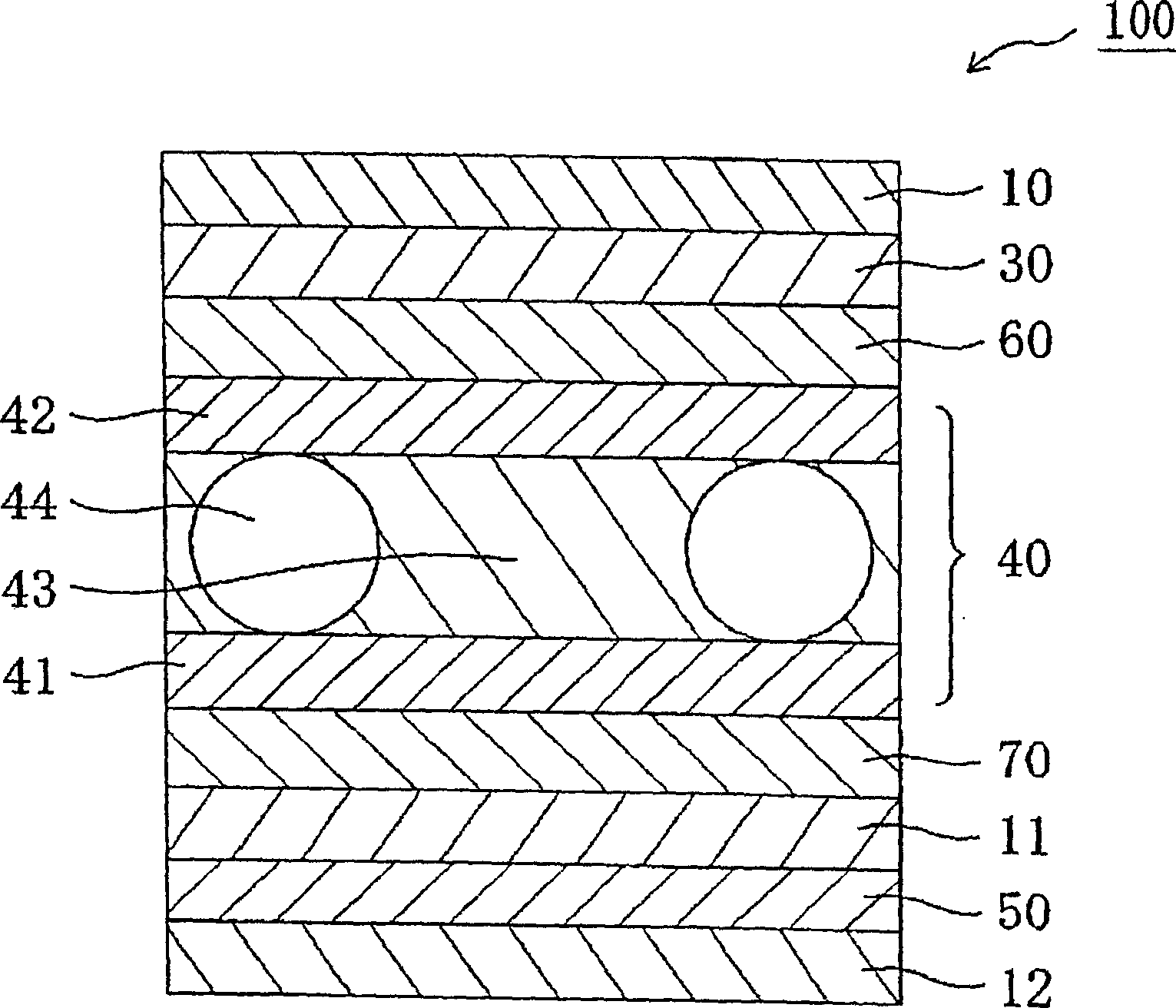
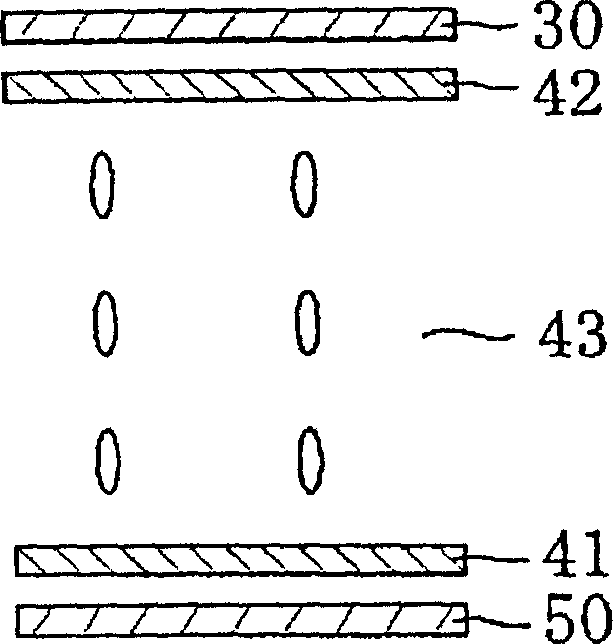
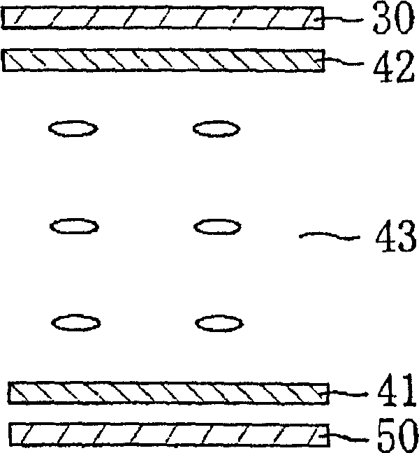
Optical film, liquid crystal panel, and liquid crystal display apparatus
一种液晶面板、光学膜的技术,应用在光学、光学元件、非线性光学等方向,达到实现厚度的效果
- Summary
- Abstract
- Description
- Claims
- Application Information
AI Technical Summary
Problems solved by technology
Method used
Image
Examples
Embodiment 1
[0259] (Manufacture of the first birefringent layer)
[0260] At 150°C, a continuous norbornene-based resin film ("ZEONOR", trade name, obtained from Zeon Co., Ltd., with a thickness of 100 μm and a photoelastic coefficient of 3.10×10 -12 m 2 / N) uniaxially stretched to 1.43 times the length, thereby producing a continuous first birefringent layer. The thickness of the first birefringent layer is 80 micrometers, the in-plane retardation Δnd is 140 nanometers, and the retardation Rth in the thickness direction is 140 nanometers.
[0261] (Manufacture of TAC / polarizer / first birefringent layer laminate)
[0262] Triacetyl cellulose (TAC) (80 μm thick) and polarizers were laminated together using an adhesive.
[0263] The surface of the first birefringent layer thus obtained was subjected to an easy-adhesive treatment (silicon primer, "APZ6661", trade name, available from Dow Corning Toray Co., Ltd., thickness of the easy-adhesive layer = 50 nm), and The first birefringent lay...
Embodiment 2
[0275] (manufacturing of liquid crystal panels)
[0276] "Laminated body of TAC / polarizer / first birefringent layer" and "laminated body of second birefringent layer / TAC / polarizer / TAC" were obtained in the same manner as in Example 1, except that the The thickness in "Manufacture of the laminated body of the second birefringent layer / TAC" of 1 was changed to 2.1 micrometers, thereby obtaining a second birefringent layer having an in-plane retardation Δnd of 0 nanometers and a retardation Rth in the thickness direction of 190 nanometers. birefringent layer.
[0277] The first birefringent layer side of the "TAC / polarizer / first birefringent layer laminate" was bonded to the "second birefringent layer / TAC / polarizer" via an acrylic pressure-sensitive adhesive (20 µm in thickness). / TAC laminate" with the second birefringent layer side attached to the upper and lower sides of the liquid crystal cell so that the absorption axes of the polarizers are perpendicular to each other. A l...
Embodiment 3
[0281] (manufacturing of liquid crystal panels)
[0282] "Laminated body of TAC / polarizer / first birefringent layer" and "laminated body of second birefringent layer / TAC / polarizer / TAC" were obtained in the same manner as in Example 1, except that the The thickness in "Manufacture of the laminated body of the second birefringent layer / TAC" of 1 was changed to 2.1 micrometers, thereby obtaining a second birefringent layer having an in-plane retardation Δnd of 0 nanometers and a retardation Rth in the thickness direction of 195 nanometers. birefringent layer.
[0283] The first birefringent layer side of the "TAC / polarizer / first birefringent layer laminate" was bonded to the "second birefringent layer / TAC / polarizer" via an acrylic pressure-sensitive adhesive (20 µm in thickness). / TAC laminate" with the second birefringent layer side attached to the upper and lower sides of the liquid crystal cell so that the absorption axes of the polarizers are perpendicular to each other. A l...
PUM
| Property | Measurement | Unit |
|---|---|---|
| angle | aaaaa | aaaaa |
| drawing temperature | aaaaa | aaaaa |
| birefringence | aaaaa | aaaaa |
Abstract
Description
Claims
Application Information
 - R&D Engineer
- R&D Manager
- IP Professional
- Industry Leading Data Capabilities
- Powerful AI technology
- Patent DNA Extraction
Browse by: Latest US Patents, China's latest patents, Technical Efficacy Thesaurus, Application Domain, Technology Topic.
© 2024 PatSnap. All rights reserved.Legal|Privacy policy|Modern Slavery Act Transparency Statement|Sitemap


