
Substrate processing device

A substrate processing device and substrate technology, applied in the direction of transportation and packaging, conveyor objects, electrical components, etc., can solve the problems of non-floating substrates and increased device costs, and achieve the effects of preventing fracture and suppressing bending stress

Active Publication Date: 2006-11-01
DAINIPPON SCREEN MTG CO LTD
View PDF2 Cites 11 Cited by
  • Summary
  • Abstract
  • Description
  • Claims
  • Application Information

AI Technical Summary

Problems solved by technology

[0011] However, in the technique described in the aforementioned Patent Document 1, since a plurality of driving mechanisms are provided, there is a problem that the cost of the device increases.
[0012] In addition, in the technique described in the above-mentioned Patent Document 2, since the support pin is pressed against the back surface of the substrate by the urging force of the spring, there is a period during which the substrate is supported on the support table, and suction needs to be performed so that the substrate does not float. question

Method used


Image

  • Substrate processing device
  • Substrate processing device
  • Substrate processing device

Examples


no. 3 approach

[0117] In the first embodiment, an example in which the raising and reinforcing member 354 and the fixing plate 350 are formed of different members and separated from the raising and reinforcing member 354 and the fixing plate 350 at the raised position has been described, but the fixing plate 350 may also have a raised reinforcing The function of component 354.

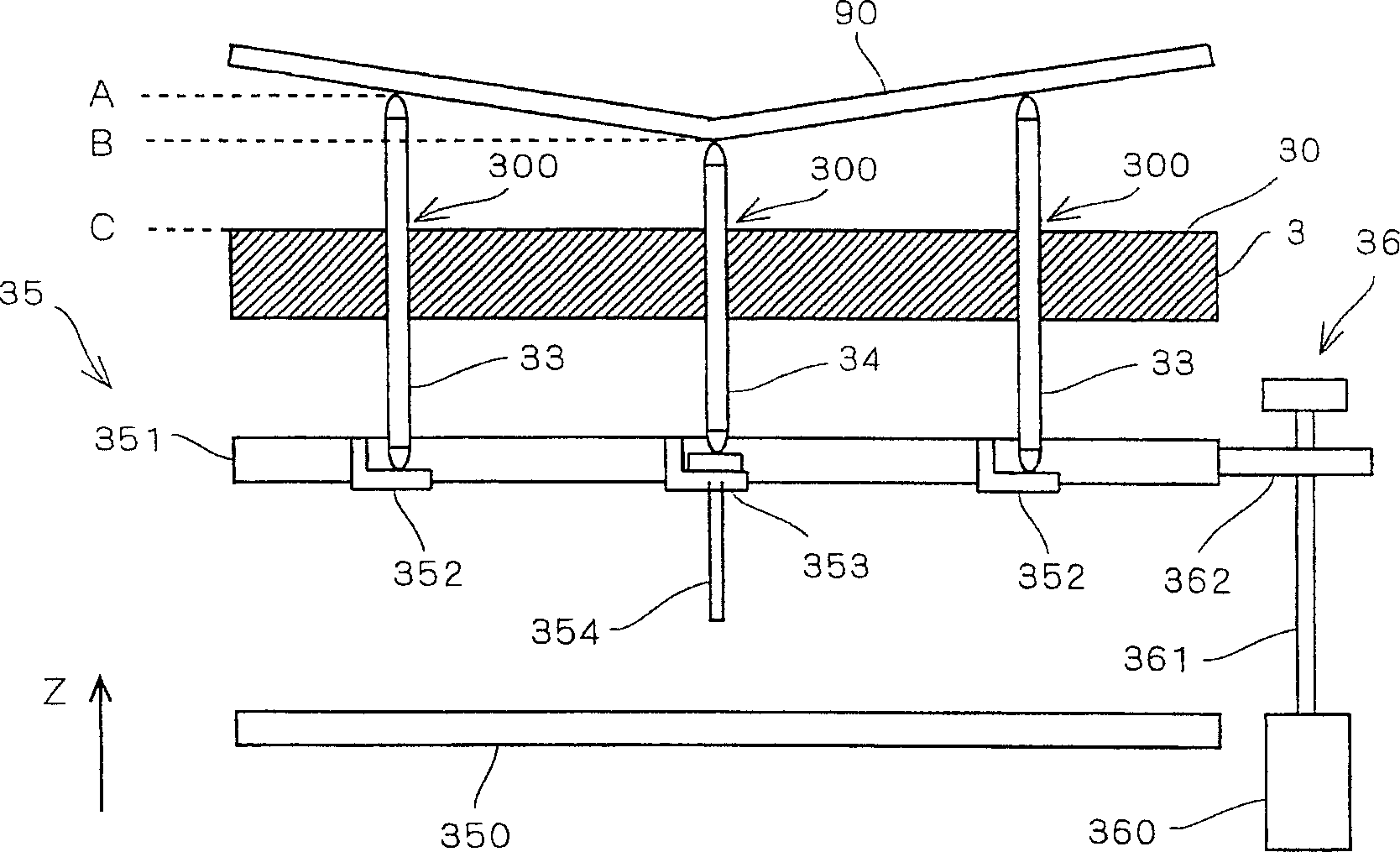
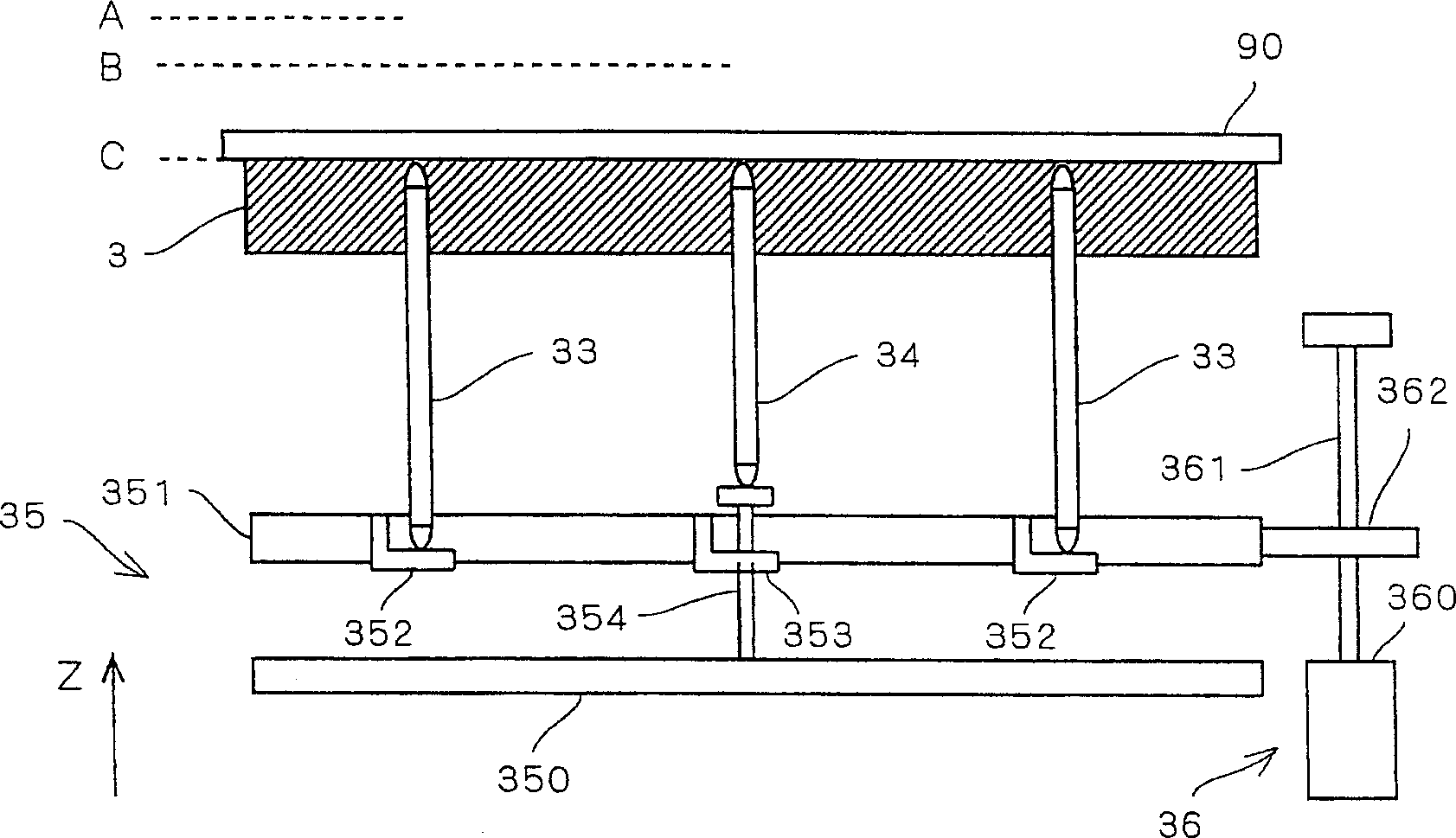
[0118] Image 6 It is a figure which shows the state which supports the 1st support pin 33 and the 2nd support pin 34b at the raised position by the pin support mechanism 35b of the substrate processing apparatus 1b in 3rd Embodiment. in addition, Figure 7 It is a figure which shows the state in which the pin support mechanism 35b supports the 1st support pin 33 and the 2nd support pin 34b at a lowered position.

[0119] The pin support mechanism 35b of 3rd Embodiment has the fixing plate 350a which formed the pin-shaped raising reinforcement member 350b. The raising reinforcing member 350b is formed in a protrud...


PUM


Abstract

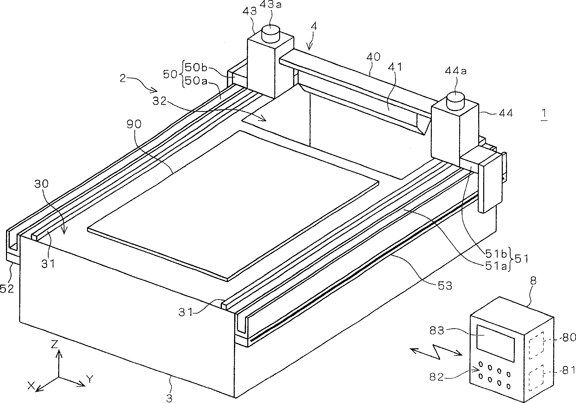
An object of the present invention is to provide a mechanism that properly supports the substrate on a support table during processing of the substrate, while also properly handling the substrate when the substrate is loaded onto or lifted from the support table. A first support pin (33) in contact with the peripheral portion of the base plate (90) and a second support pin (34) in contact with the central portion of the base plate are provided. The lower end of the first support pin is supported by a sliding contact plate (352) fixedly arranged on the lift plate (351), and the lower end of the second support pin is supported by a raising and reinforcing member (354). The lower part of the elevating reinforcement member is arranged so as to penetrate through a sliding contact plate (353) fixed on the lift plate, and is supported freely up and down within a predetermined range with respect to the lift plate. It is designed in such a manner that the size of the second support pin and the up-down direction of the raising reinforcement member is equal to the size from the holding surface (30) to the upper surface of the fixing plate (350).

Description

technical field [0001] The present invention relates to a technology for carrying a substrate into a support table and a technology for carrying out a substrate from the support table when the substrate is loaded on the support table for processing. Background technique [0002] In the prior art, there is proposed a substrate processing apparatus that horizontally supports a substrate by a support table and performs various processes on the substrate. In such a substrate processing apparatus, a plurality of support pins that are raised and lowered is provided, and the carried-in substrate is loaded on the plurality of support pins that are raised, and the support pins are lowered and embedded in the support table to be loaded on the support table. In addition, the processed substrate is raised by the support pins and protrudes upward from the support table to be lifted from the support table and carried out. [0003] With this structure, when the substrate is loaded on the ...

Claims


Application Information

Patent Timeline
IPC IPC(8): H01L21/687H01L21/00H01L21/67H01L21/677
Inventor 柿村崇山本广
Owner DAINIPPON SCREEN MTG CO LTD
Learn More