
Planar monopole antenna

A monopole antenna, planar technology, applied in resonant antenna, antenna grounding device, radiating element structure and other directions, can solve the problems of low bandwidth coverage, unsatisfactory antenna transmission and reception effect, etc.

Inactive Publication Date: 2006-11-01
WISTRON NEWEB
View PDF0 Cites 5 Cited by
  • Summary
  • Abstract
  • Description
  • Claims
  • Application Information

AI Technical Summary

Problems solved by technology

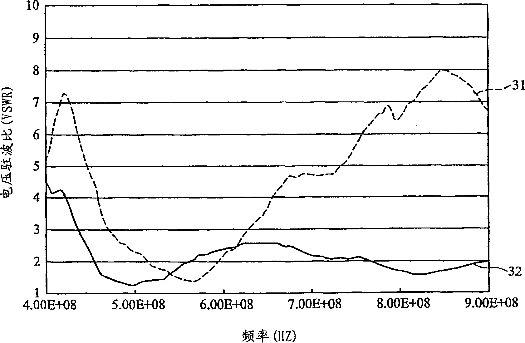
[0005] For digital video broadcasting (Digital Video Broadcasting, DVB) which is generally about 460-860MHz, the bandwidth coverage of traditional planar monopole antennas is mostly lower than 30%, so the transmission and reception effects of the antenna are not ideal

Method used


Image

  • Planar monopole antenna
  • Planar monopole antenna
  • Planar monopole antenna

Examples


Embodiment Construction

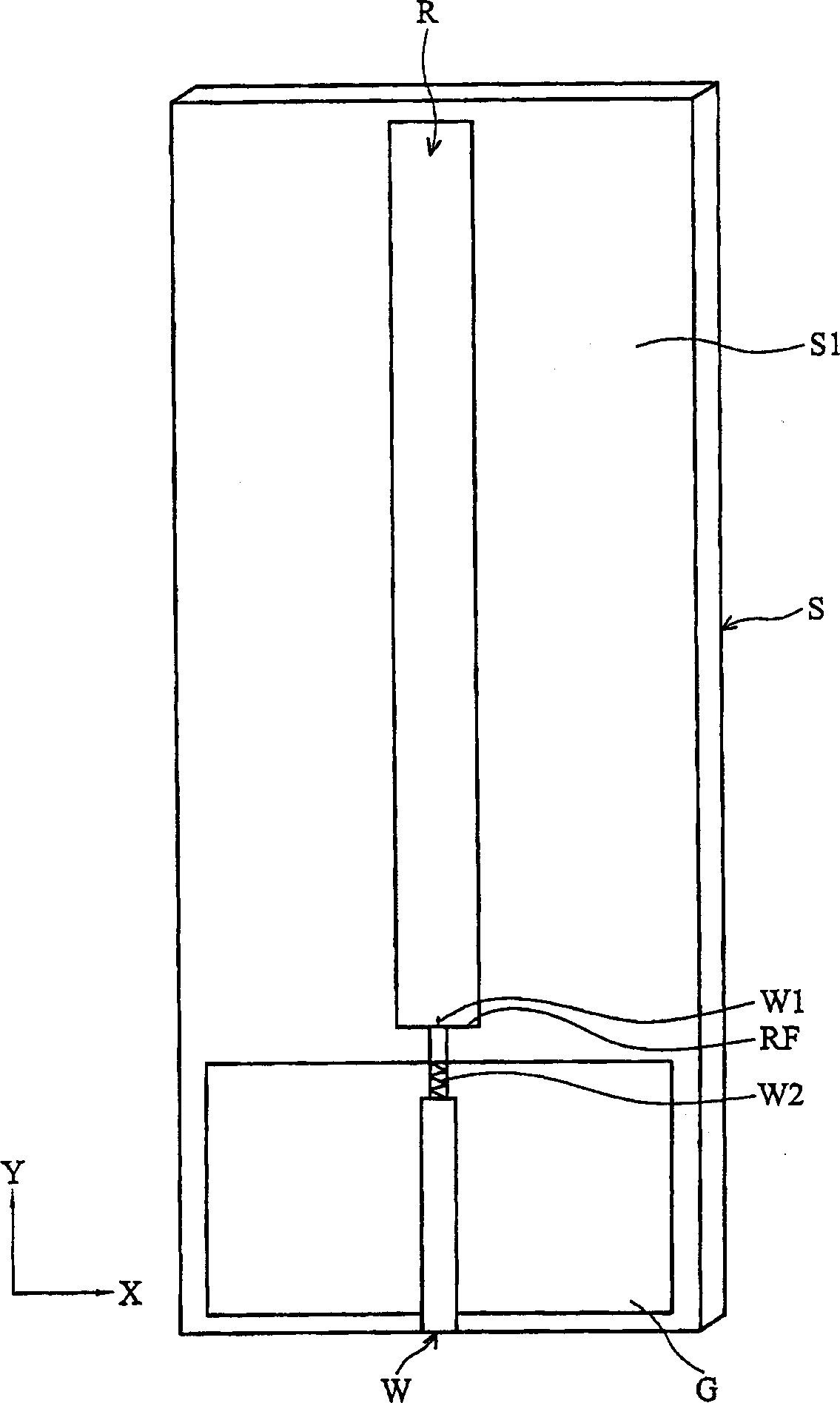
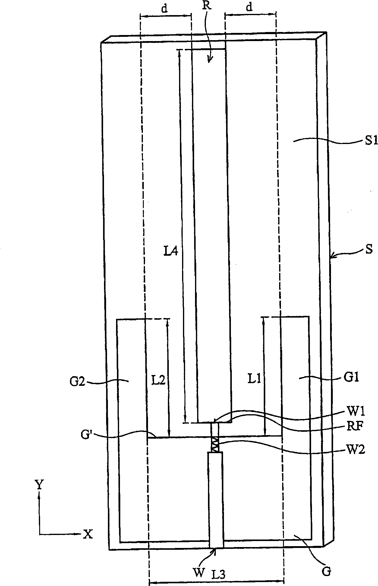
[0024] see figure 2 , which shows a schematic diagram of the planar monopole antenna of the present invention. As shown in the figure, the planar monopole antenna of the present invention can transmit wireless signals within a specific frequency range, and mainly includes a substrate S, a ground metal G, a first sleeve G1, a first Two sleeve-shaped structures G2, a radiator R and a cable W, the ground metal G and the radiator R are formed on the surface S1 of the substrate S, wherein the radiator R is elongated and faces a first direction (Y-axis direction ) extension, and a feed-in terminal RF located below the radiator R is adjacent to one side G′ of the ground metal G. In this embodiment, the above-mentioned cable W is a coaxial cable, including a signal wire W1 and a ground wire W2, the above-mentioned ground wire W2 is wrapped around the periphery of the signal wire W1, wherein the signal wire W1 is connected to the bottom of the radiator R. The feed-in terminal RF, an...


PUM


Abstract

A planar monopole antenna comprises: a baseboard, a ground metal, a first sleeve like structure, a second sleeve like structure and a radiator. Said ground metal is formed in said baseboard, and said first and second sleeve like structures are connected to the ground metal, and are extended from one side edge of said ground metal to a first direction. In the first direction, said first and second sleeve like structures respectively have a first and a second length, and said side edge has a third length. Said radiator is formed on said baseboard and is located between said first and second structures. Said radiator shows a strip -like shape, and in the first direction has a fourth length equaling the sum of said first, second and third lengths.

Description

technical field [0001] The invention relates to a planar monopole antenna, in particular to a planar monopole antenna with a sleeve structure. Background technique [0002] With the rapid development of wireless communication and the trend of miniaturization of communication products, some embedded micro-antennas have emerged as the times require. At present, the commonly used micro-antennas include chip antennas (chipantenna) and planar antennas (planar antennas). )wait. Generally speaking, these types of antennas have the characteristics of small size, among which common chip antennas are ceramic chip antennas (ceramic chip antennas) made of co-fired ceramic technology (LTCC), and there are many planar antenna designs, such as micro Strip antenna (microstripe antenna), printed antenna (printed antenna) and planar inverted F antenna (Planar Inverted F Antenna, PIFA), etc., these antennas are widely used in GSM, DCS, UMTS, WLAN and Bluetooth, etc. Wireless terminal equipme...

Claims


Application Information

Patent Timeline
IPC IPC(8): H01Q9/30H01Q1/38
CPCH01Q9/40H01Q1/38H01Q1/48H01Q9/36
Inventor 陈志龙刘志凯
Owner WISTRON NEWEB
Learn More