TV antenna structure

A technology for TV antennas and tubular components, which is applied to antennas, electrical components, etc., can solve the problems of not beautiful and practical appearance, poor corrosion resistance, and high cost, so as to improve the bending resistance section modulus, improve the bending resistance ability and beautiful appearance. Effect

Inactive Publication Date: 2006-11-01
上海温兴生物工程有限公司
View PDF0 Cites 0 Cited by
  • Summary
  • Abstract
  • Description
  • Claims
  • Application Information

AI Technical Summary

Problems solved by technology

[0003] The purpose of the present invention is to provide a structure of TV antenna, the structure of this TV antenna will solve the problem that in the prior art, the main components of TV antenn

Method used


Image

  • TV antenna structure
  • TV antenna structure
  • TV antenna structure

Examples


Example Embodiment

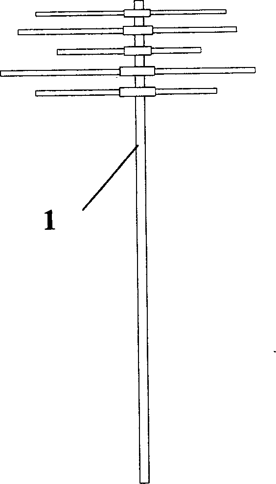
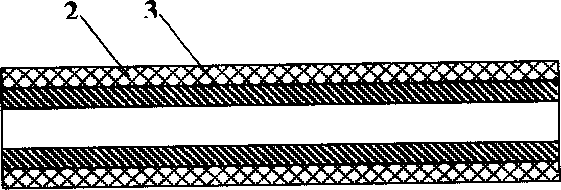
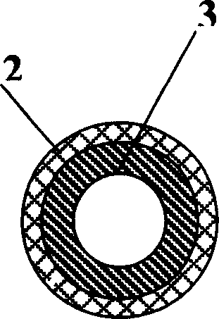
[0011] Such as figure 1 , figure 2 with image 3 As shown, the structure of a television antenna of the present invention is composed of at least one tubular member 1, and the tubular members 1 are fixedly connected, wherein any one of the tubular members 1 is made of a stainless steel tube body 2. Structure, any one of the stainless steel pipe body 2 is provided with a reinforced fiber plastic pipe body 3, and the diameter of the reinforced fiber plastic pipe body 3 matches the diameter of the stainless steel pipe body 2. The pipe body 2 and the reinforced fiber plastic pipe body 3 are fixedly connected.

[0012] Further, the radial cross-section of the tubular member 1 is circular, rectangular, square, or special-shaped.

[0013] Further, the tubular members 1 are connected by a thin-walled connector, and the thin-walled connector and the tubular member 1 are connected by a welding structure, a riveting structure, or an adhesive structure.


PUM


Abstract

A TV antenna structure comprises more than one tube like components, which are connected together in a securing state. Wherein each said tube is made of stainless steel, and inside each said tube there is a fiber-reinforced plastic pipe having a diameter matching the diameter of said stainless steel tube. Said stainless steel tube and the said fiber-reinforced plastic pip are jointed together in a securing state.

Description

technical field [0001] The invention relates to a TV wireless receiving device, in particular to a TV antenna, in particular to a TV antenna structure. Background technique [0002] At present, with the continuous advancement of my country's economic construction, urban infrastructure construction is also in full swing. Although the penetration rate of cable TV in my country's cities has been greatly improved, and cable TV has been basically popularized in cities and many towns, our country has a vast territory and many The reception of cable television has not been popularized in rural areas, so there is a great demand for wireless receiving devices, especially TV antennas. However, the main components used in TV antennas are mainly made of various stainless steel and aluminum alloys. , and the cost is high, not corrosion-resistant, and the appearance is not beautiful enough. Contents of the invention [0003] The purpose of the present invention is to provide a structure ...

Claims


Application Information

Patent Timeline
IPC IPC(8): H01Q19/04
Inventor 陈宏强王耀庭
Owner 上海温兴生物工程有限公司
Why Eureka
Try Eureka