


Quick Research
Generate reliable direction feasibility study reports for your R&D in just a few steps.

Technical Q&A
Discover and master advanced knowledge NOW. Basics, ideas, possibilities, all at once.

Find Solutions
As an expert in R&D theories, this can generate solutions to your technical problems instantly.

Evaluate Feasibility
Analyze your overall solution with one click, know your potential R&D risks in advance.

Monitor Landscape
Get weekly tech updates, stay abreast of the latest tech innovations and key insights.
Thermistor
一种热敏电阻器、电阻部的技术,应用在热敏电阻器、电阻器、不可调金属电阻器等方向,能够解决制造成本增加、模块大型化、结构复杂等问题,达到制造成本抑制、零件数量少、工作速度和工作精度高的效果
- Summary
- Abstract
- Description
- Claims
- Application Information
AI Technical Summary
Problems solved by technology
Method used
Image

Examples
no. 1 Embodiment approach
[0023] exist Figure 1 ~ Figure 2 1st Embodiment of this invention is shown and demonstrated in .
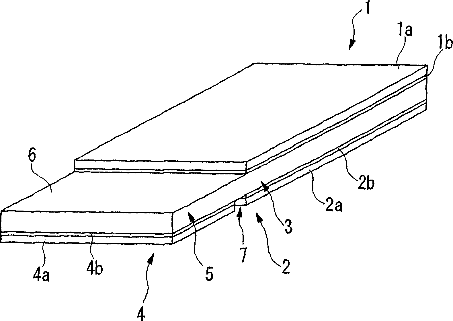
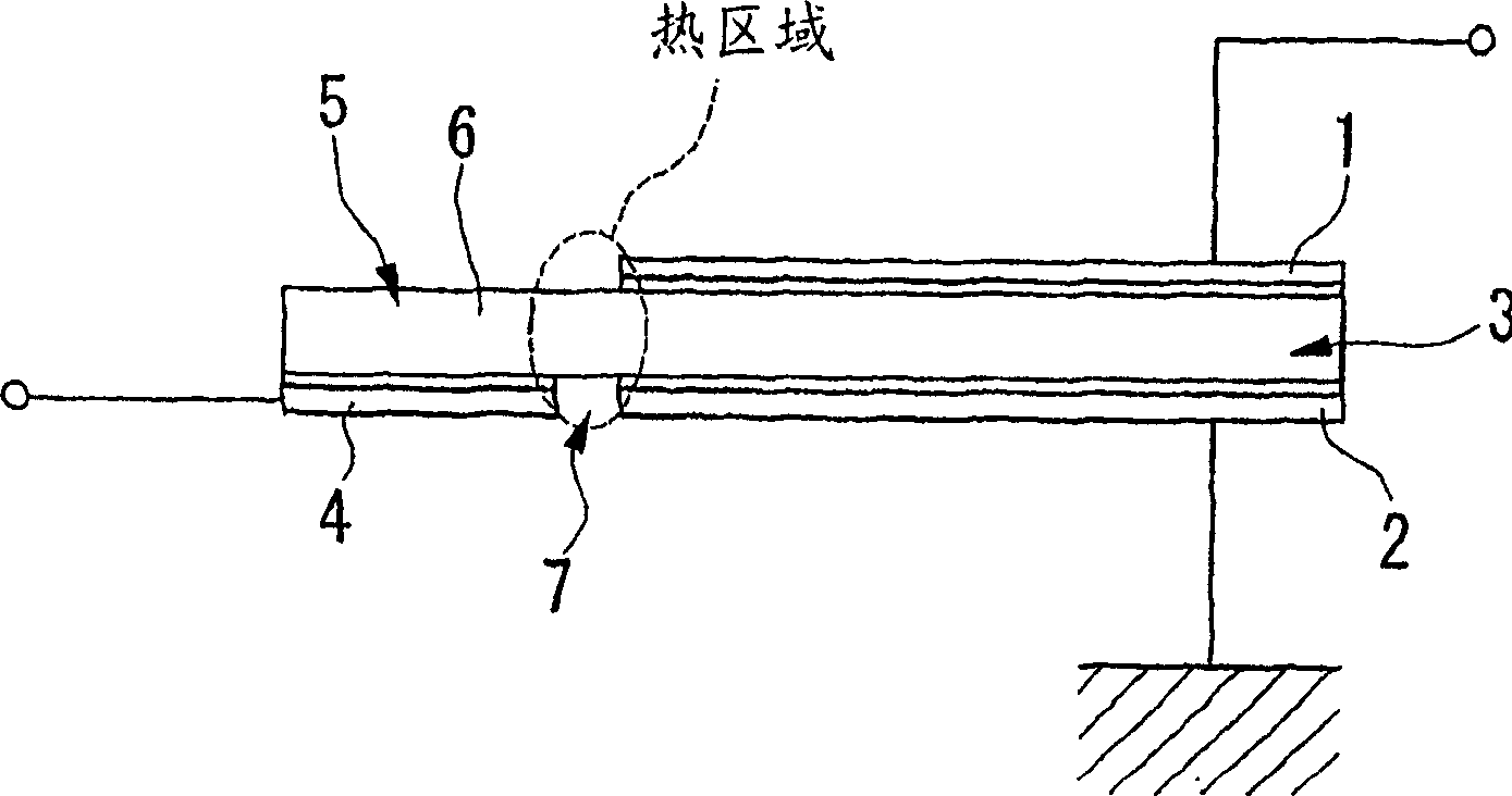
[0024] exist Figure 1 ~ Figure 2 , shows a polymer PTC thermistor as an overcurrent protection element. The polymer PTC thermistor includes: 2 electrodes (1st, 2nd electrodes) 1, 2; a variable resistor installed between these two electrodes 1, 2, using temperature changes to change the resistance value Part 3; an electrode (third electrode) 4 that is not in contact with any of the electrodes 1 and 2; is integrally formed with the same material as the varistor part 3, and is in contact with the electrode 4. A current flows between the electrode 4 and the electrode 2 to generate heat to change the resistance value of the variable resistance part 3 in the heating part 5 . The varistor part 3 and the heat generating part 5 correspond to two non-overlapping parts of the conductive polymer 6 formed in a plate shape.
[0025] The conductive polymer 6 is rectangular and plate-like ...
no. 2 Embodiment approach
[0034] then, Figure 3 ~ Figure 5 The 2nd embodiment of this invention is shown and demonstrated in . In addition, the same code|symbol is attached|subjected to the component already demonstrated in the said embodiment, and description is abbreviate|omitted.
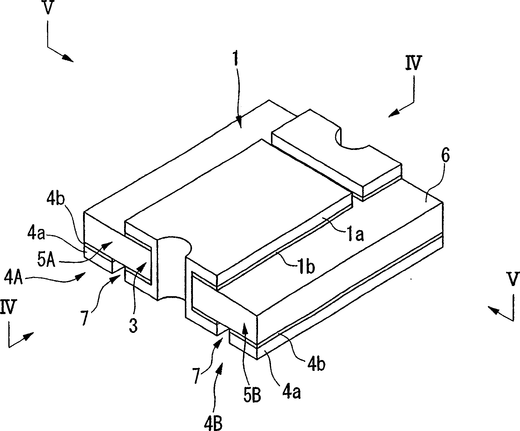
[0035] exist Figure 3 ~ Figure 5 Each figure in FIG. 1 shows a polymer PTC thermistor as an overcurrent protection element similarly to the first embodiment. This polymer PTC thermistor has the same rectangular and plate-shaped conductive polymer 6 as in the first embodiment, but in this embodiment, the variable resistance part 3 is arranged in the center, and two heat generating parts 5A, 5B are respectively provided on both sides thereof, and electrodes 4A, 4B as third electrodes are respectively provided on the respective heat generating parts 5A, 5B.
[0036] Most of the electrode 1 is arranged on one side of the central part of the variable resistance part 3 in the conductive polymer 6 ( image 3 The middle is ...
no. 3 Embodiment approach
[0040] then, Figure 6 ~ Figure 7 The 3rd embodiment of this invention is shown and demonstrated in . In addition, the same code|symbol is attached|subjected to the component already demonstrated in the said embodiment, and description is abbreviate|omitted.
[0041] exist Figure 6 ~ Figure 7 Each figure in FIG. 1 shows a polymer PTC thermistor as an overcurrent protection element similarly to the first and second embodiments. This polymer PTC thermistor is different from the above-mentioned embodiment in that it has a circular and plate-shaped conductive polymer 6, the variable resistance part 3 is arranged in the center, and the heat generating part 5C is arranged around it. Electrodes 4C serving as third electrodes are provided on both sides of the heat generating portion 5C.
[0042] The electrode 1 is arranged on one side of the central part constituting the variable resistance part 3 in the conductive polymer 6 ( Figure 6 On the upper surface side in the middle), t...
PUM
 Abstract
Description
Claims
Application Information
 - R&D Engineer
- R&D Manager
- IP Professional
- Industry Leading Data Capabilities
- Powerful AI technology
- Patent DNA Extraction
Browse by: Latest US Patents, China's latest patents, Technical Efficacy Thesaurus, Application Domain, Technology Topic, Popular Technical Reports.
© 2024 PatSnap. All rights reserved.Legal|Privacy policy|Modern Slavery Act Transparency Statement|Sitemap|About US| Contact US: help@patsnap.com