
Steering system with leads and pulls compensation

一种助力转向、拉力的技术,应用在动力转向机构、转向机构、转向拉杆等方向,能够解决缺少分析能力、未监控转向输出等问题

Active Publication Date: 2006-11-08
GM GLOBAL TECH OPERATIONS LLC
View PDF4 Cites 16 Cited by
  • Summary
  • Abstract
  • Description
  • Claims
  • Application Information

AI Technical Summary

Problems solved by technology

However, the system lacks analytical capabilities, especially for the state of vehicle tension, as it does not monitor the steering output

Method used


Image

  • Steering system with leads and pulls compensation
  • Steering system with leads and pulls compensation
  • Steering system with leads and pulls compensation

Examples


Embodiment Construction

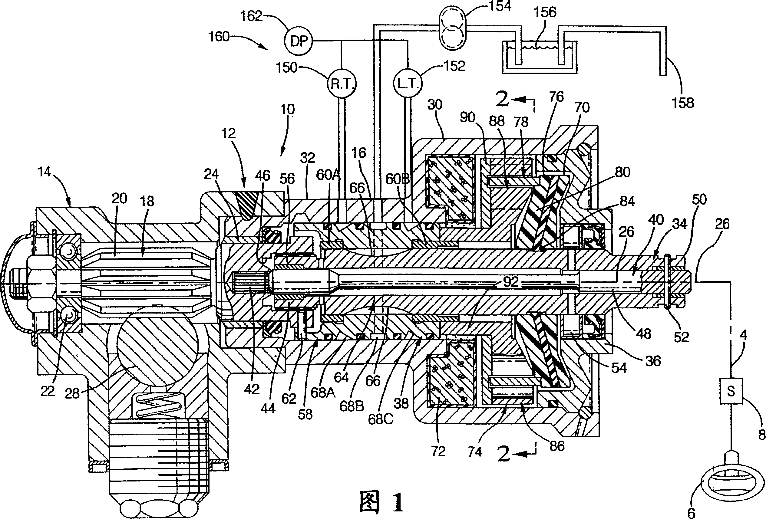
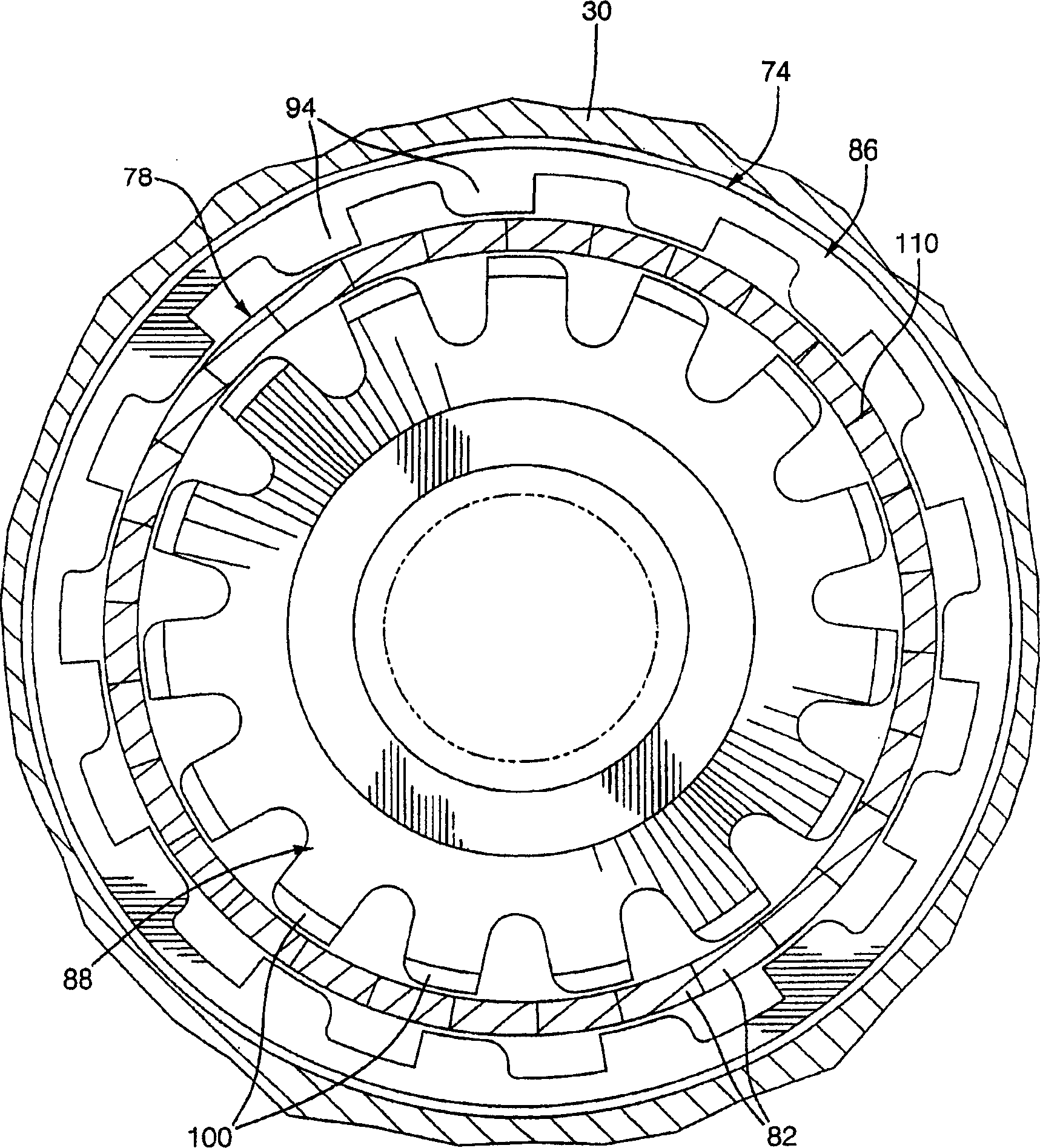
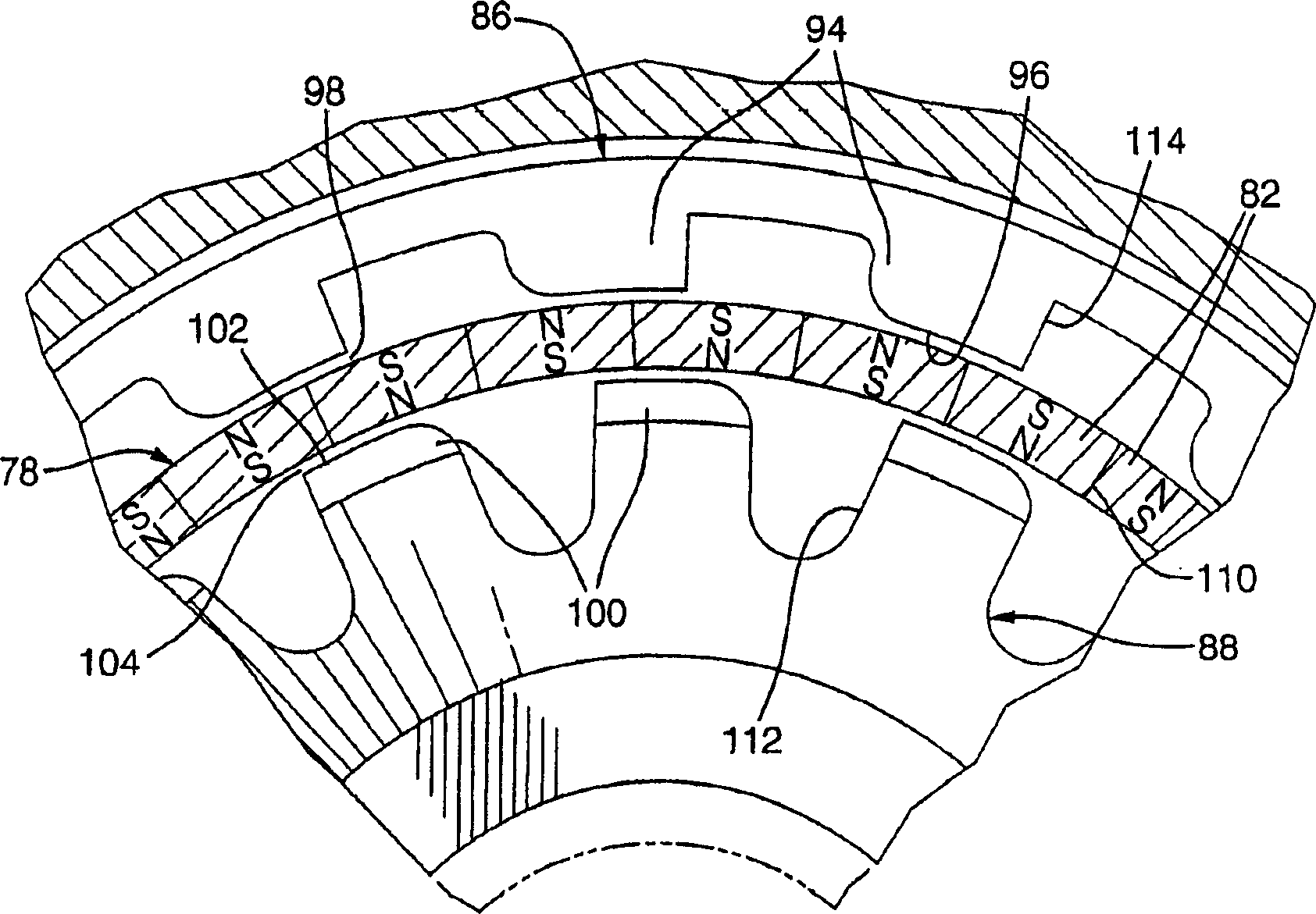
[0021] Referring to FIG. 1 , a motor vehicle power steering driveline 10 , disclosed in part in U.S. Patent No. 5,119,898 , the contents of which is incorporated herein by reference, includes a composite housing 12 having a rack housing 14 and a valve housing 16 . Driver input is provided through handwheel 6 connected to power steering driveline 10 via steering shaft 4 . It should be understood that the steering shaft 4 may include first and second shafts, or other structures may be selected to connect the handwheel (or called steering wheel) 6 to the power steering transmission system 10 . A position sensor 8 may be arranged relative to the handwheel 6 to detect the position of the handwheel 6 to provide an indication of operator input. The position signal is sent to the controller for processing, as described further below. Steering wheel speed can be determined within the controller using the position signal. The pinion 18 having a plurality of gear teeth 20 is supported...


PUM


Abstract

A power assist steering system including a valve housing and a proportional control valve supported within the valve housing, further includes a pressure transducer arranged with respect to the proportional control valve for determining an amount of actuation of the proportional control valve. A pressure signal is sent from the pressure transducer to a control for determining an amount of current to be sent to an electromagnetic apparatus within the power assist steering system for overcoming a pull force.

Description

technical field [0001] The present invention relates generally to a vehicle steering apparatus, and in particular, the present invention relates to a vehicle steering apparatus with variable power steering. Background technique [0002] A motor vehicle can experience a state of pull where the driver of the vehicle must input torque into the steering system in order for the vehicle to maintain a straight line. Pull state can be determined by the vehicle, road conditions and weather conditions, such as crosswind, which requires steering system input force to overcome; valve builds up pressure in the system), which requires driver input torque to correct. [0003] US Patent No. 5,749,432 discloses a variable power steering system capable of providing torque to an input shaft without driver input. The patent shows angle sensors on the top and bottom of the valve assembly to provide a signal representing the angle of rotation of the spool valve shaft, and a magnetic ring to con...

Claims


Application Information

Patent Timeline
Patent Type & Authority Applications(China)
IPC IPC(8): B62D6/00B62D5/06
CPCB62D5/0835B62D6/04B60W2710/20
Inventor J·E·比尔兴H·杨M·P·舍里丹S·J·赖德尔J·M·鲍威尔
Owner GM GLOBAL TECH OPERATIONS LLC
Learn More