Method for realizing line differential protection based on long line equation

A technology of long-line equations and lines, applied in the field of power systems, can solve problems affecting the safety of current differential protection, reliability of internal faults, large distributed capacitance current, and influence of differential protection, etc.

Active Publication Date: 2006-11-08
BEIJING SIFANG JIBAO AUTOMATION +1
View PDF0 Cites 21 Cited by
  • Summary
  • Abstract
  • Description
  • Claims
  • Application Information

AI Technical Summary

Problems solved by technology

[0007] On ultra-high voltage and ultra-high voltage long lines, the distributed capacitance current is extremely large, which greatly affects the safety of current differential protection in the event of external faults and the reliability of internal faults
Based on the centralized parameters, the distributed capacitive current at the protection installation is compensated by the braking criterion of

Method used


Image

  • Method for realizing line differential protection based on long line equation
  • Method for realizing line differential protection based on long line equation

Examples


Embodiment Construction

[0018] specific implementation plan

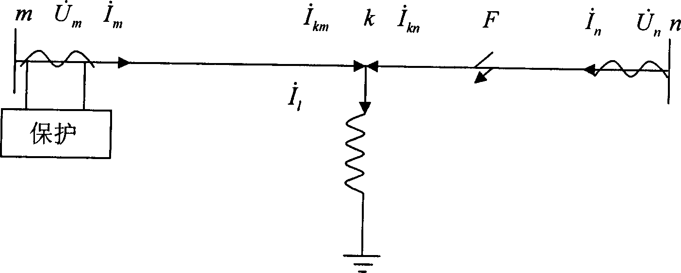
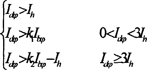
[0019] First use the long-term equation to protect the installation place (take the m terminal as an example) voltage electric current Converted to the reference point k in the way of phasor calculation, with Indicates that the n-terminal converted reference point is Indicates that if there is a shunt reactor, the current of the shunt reactor needs to be removed first to obtain Then do the required calculation for differential protection according to formula (1).

[0020] I d > I h I d > k 1 I b ...


PUM


Abstract

This invention relates to a relay protection method in a power system and discloses a method for realizing circuit differential protection based on the long-line equation computation in a high voltage transmission circuit, which converts the voltage and current tested at the protection mounted place to those of a reference point K in the protection sphere by a method of vector computing long-line equation, in which, the voltage Um and the current Im of end m are voltage UKm and current IKm converted to point K, the current In is converted to point k as voltage Ukn and cutrrent Ikn, if there are parallel reactors, it's needed to deduct the current on it to get I'km and I'kn, then Ikm, Ikn or I'km applied at the reference point and the I'kn is computed in terms of multiple differential formula to judge if there is fault in the region.

Description

technical field [0001] The invention relates to the field of power systems, more specifically to a relay protection method, and to an algorithm for line phase-separated current differential protection. Background technique [0002] Transmission line is the basic equipment for power generation and transmission in the power system, and occupies a very important position in the power system. When the transmission line is faulty, if it cannot be cut off in time or by mistake, it will have a great impact on the main system, and it will easily cause major accidents such as grid splitting and transformer tripping. High-voltage line protection undertakes the important task of power transmission and is an important hub of the power system. They are extremely expensive to manufacture, and once they are damaged due to malfunctions, they will be difficult to repair and take a long time, causing huge direct and indirect losses to the national economy. In this way, higher requirements a...

Claims


Application Information

Patent Timeline
IPC IPC(8): H02H7/26H02H3/26
Inventor 徐振宇贺家李杜兆强秦应力刘建飞孟岩魏会利
Owner BEIJING SIFANG JIBAO AUTOMATION
Why Eureka
Try Eureka