Voile dispersing mechanism for sartorius

A yarn splitter and sewing machine technology, which is applied in the direction of sewing equipment, sewing machine components, sewing machine thread take-up devices, etc., can solve problems such as inability to sew, difficult to correspond to high-speed operation of sewing machines, provocation or unstable wires, etc., to prevent unconscious The effect of jumper

A yarn splitter and sewing machine technology, which is applied in the direction of sewing equipment, sewing machine components, sewing machine thread take-up devices, etc., can solve problems such as inability to sew, difficult to correspond to high-speed operation of sewing machines, provocation or unstable wires, etc., to prevent unconscious The effect of jumper

CN1861872AInactive Publication Date: 2006-11-15MORIMOTO MFG

Image

  • Voile dispersing mechanism for sartorius
  • Voile dispersing mechanism for sartorius
  • Voile dispersing mechanism for sartorius

Examples


Embodiment Construction

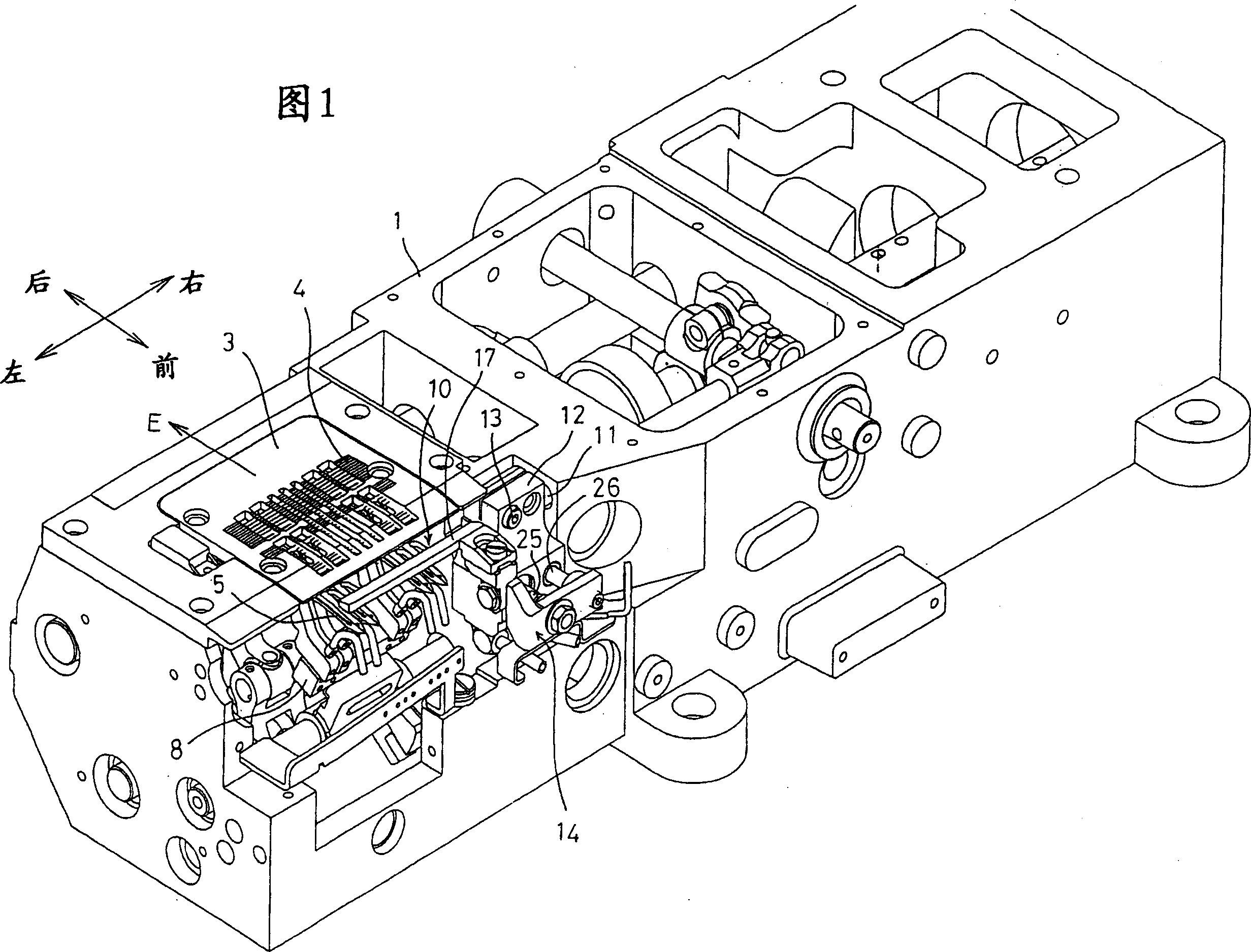
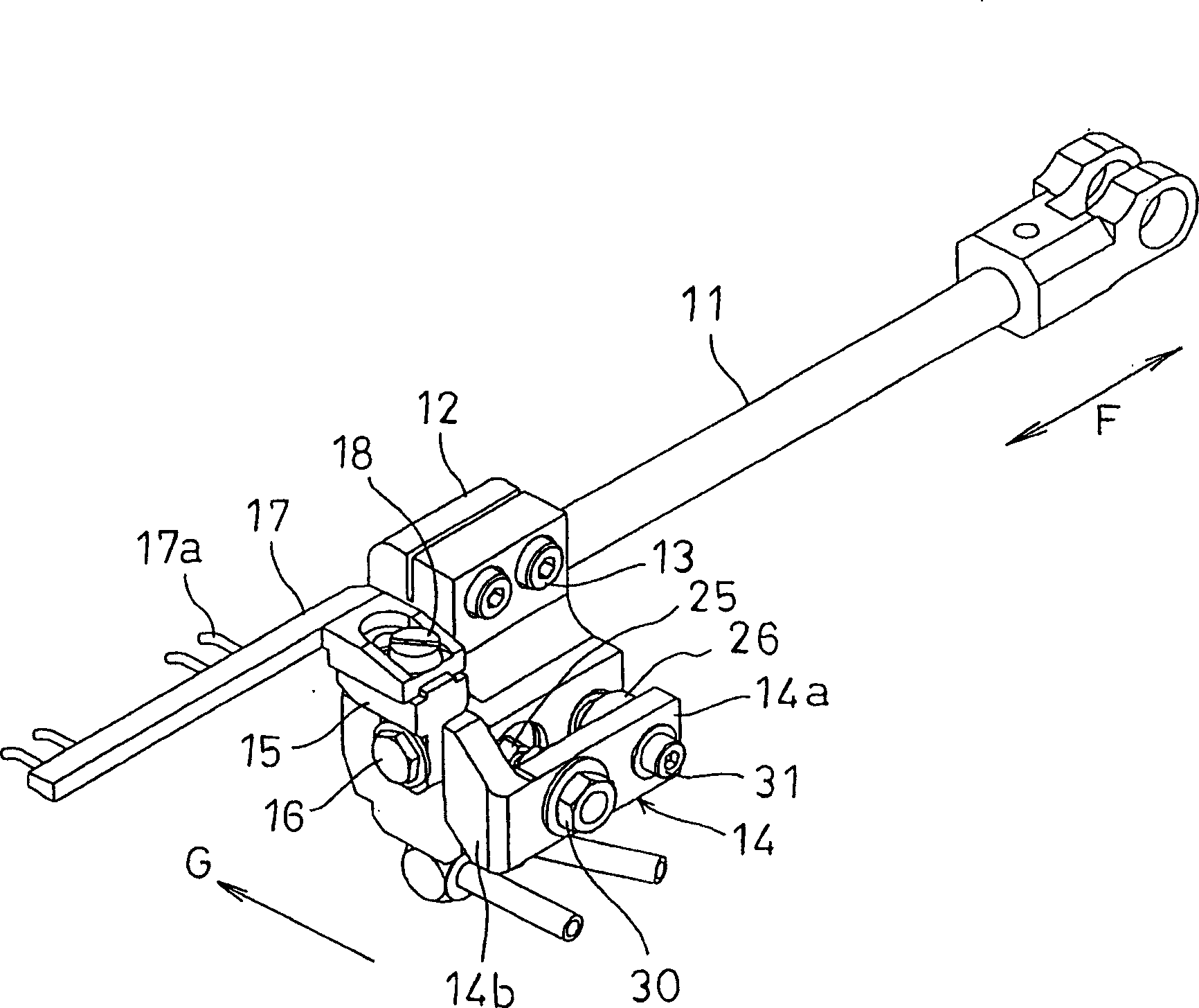
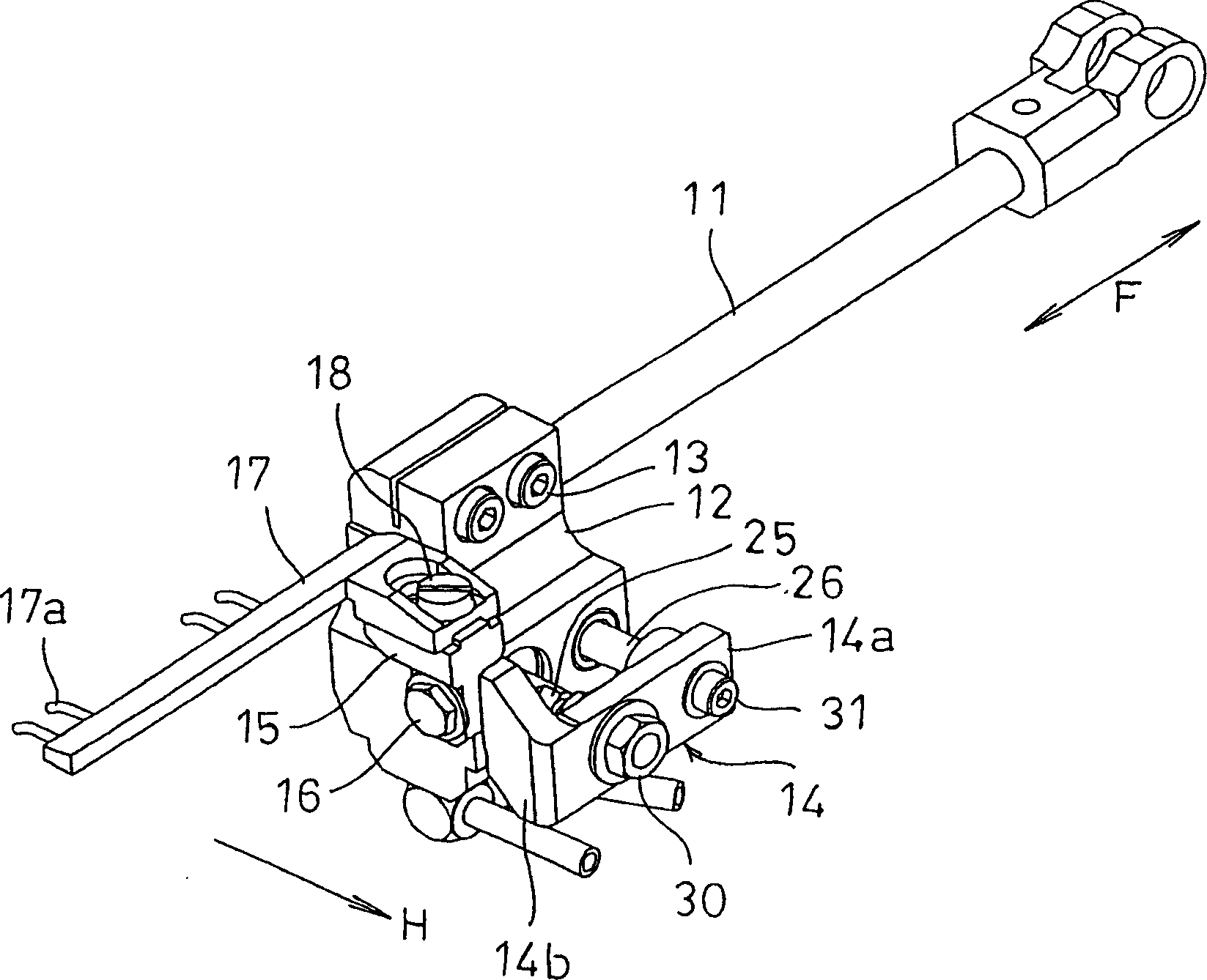
[0029] Preferred embodiments of the present invention will be described with reference to the drawings. Fig. 1 is a perspective view showing a base portion of a sewing machine having a yarn divider mechanism according to an embodiment of the present invention, figure 2 It is a perspective view showing the yarn divider mechanism in a state where the yarn divider is moved to the guide wire position, image 3 is a perspective view showing the splitter mechanism in a state where the splitter has been moved to a retracted position, Figure 4 It is a side view showing the splitter mechanism in a state where the splitter has been moved to the wire position, Figure 5 is a side view showing the splitter mechanism in a state where the splitter has been moved to a retreat position, Figure 6 It is a front view showing the yarn divider of the yarn divider mechanism, and Fig. 7(a) shows the state where the yarn divider is moved to the guide wire position. Figure 6 The X-X line sectio...


PUM


Abstract

The present invention provides a yarn divider mechanism of a sewing machine. The yarn divider of the yarn divider mechanism does not interfere with the looper, and can surely perform conscious thread skipping, and at the same time, can prevent unintentional thread skipping, and can perform proper thread skipping. sewing. It has a looper (5) and a yarn divider (17), the looper (5) is synchronized with the up and down motion of the sewing needle (2), by surrounding the looper bar (7) ) swings and engages with the upper thread to perform an elliptical motion to form stitches; the yarn divider (17) reciprocates in a left and right direction approximately perpendicular to the cloth feeding direction to pick up the bottom thread of the above-mentioned looper Lead the above-mentioned upper thread. The above-mentioned yarn divider (17) is arranged to be able to move forward and backward between the following two positions, that is, to advance in the direction G that is substantially the same as the cloth feeding direction, to carry out the wire position of the wire, and to move from the wire position. This is the retracted position for retracting in the direction opposite to the feed direction.

Description

[0001] The present invention relates to a yarn divider mechanism of a double-thread overlock sewing machine and the like, and more particularly relates to a yarn divider mechanism of a sewing machine capable of intentionally jumping threads. Background technique [0002] For efficient production, sewing of jeans, casual pants (slacks) and the like is carried out, for example, through the following steps. That is, as shown in FIG. 8 , insert the end portion of the front and rear body panels 101 into the opening of the elongated belt panel 100 having a substantially U-shaped cross section, and the front and rear body panels 101 ... and the waist belt panel 100 are inserted into the opening. Only the predetermined distance A is sewn, then a jumper portion (non-sewn portion) where only the predetermined distance B is not sewn is formed, and only the predetermined distance A is sewn again, so that the sewing is continuously performed by so-called intermittent sewing. Then, in order...

Claims


Application Information

Patent Timeline
15 Nov 2006
Publication
CN1861872A
IPC
D05B1/10; D05B49/00
Inventors
松崎博志; 森本邦彦