Float-type drop energy-eliminating noise-reducing device

A floating, noise-reducing technology, which is applied in the direction of sound-emitting devices and instruments, can solve the problems of noise pollution, secondary noise, non-acceptance, etc., and achieve stable noise-reduction effects and reduce water-falling noise

Inactive Publication Date: 2006-11-15
常州金坛塑料厂
View PDF1 Cites 12 Cited by
  • Summary
  • Abstract
  • Description
  • Claims
  • Application Information

AI Technical Summary

Problems solved by technology

For existing cooling towers, noise reduction technical transformation must also be carried out within a time limit, otherwise production must be stopped for rectification, and the noise will not be accepted if the noise does not meet the standard
At present, most of the cooling towers in power plants use fiber mesh noise reduction pads to reduce noise. The falling water directly hits the noise reduction pads. The noise reduction effect is not obvious, and the mesh is small and easily blocked by impurities.
The noise generated by existing cooling towers has seriously affected people's living and working environment quality, and has become a source of noise pollution in the new era
In order to effectively reduce the water falling noise of the cooling tower, our factory discloses a cooling tower falling water noise reducer in the patent No. 01230431. Although the noise reducer adopts the principle of slope noise reduction, so that the falling water is in contact with the slope of the honeycomb panel, its noise reduction effect is greatly improved compared with the conventional mesh noise reduction pad, but it lacks the falling water energy dissipation structure and will generate secondary noise
The noise reduction device containing the falling water noise reducer of the cooling tower is fixed above the pool. Since the device is fixed above the water pool through the fixing frame, in actual use, the distance between the lower end of the falling water noise reducer and the water surface of the pool varies with the water level of the pool. The noise reduction effect of this kind of falling water noise reduction device is unstable, and it is difficult to achieve the best noise reduction effect

Method used


Image

  • Float-type drop energy-eliminating noise-reducing device
  • Float-type drop energy-eliminating noise-reducing device
  • Float-type drop energy-eliminating noise-reducing device

Examples


specific Embodiment approach

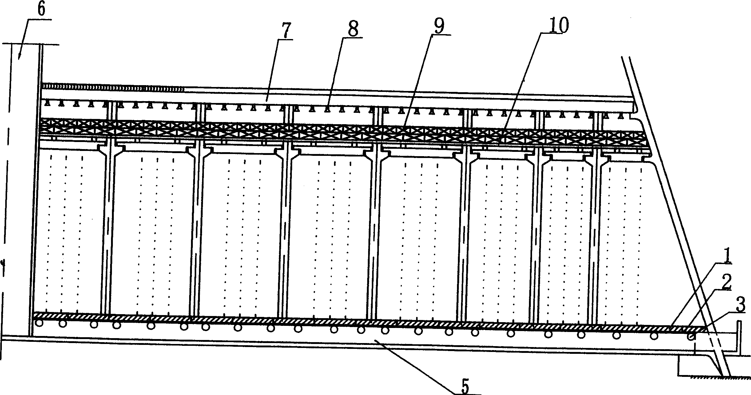
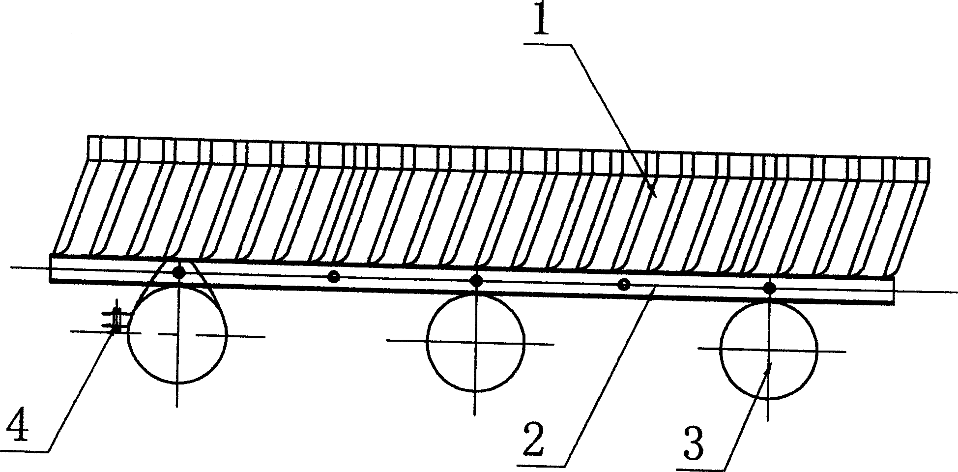
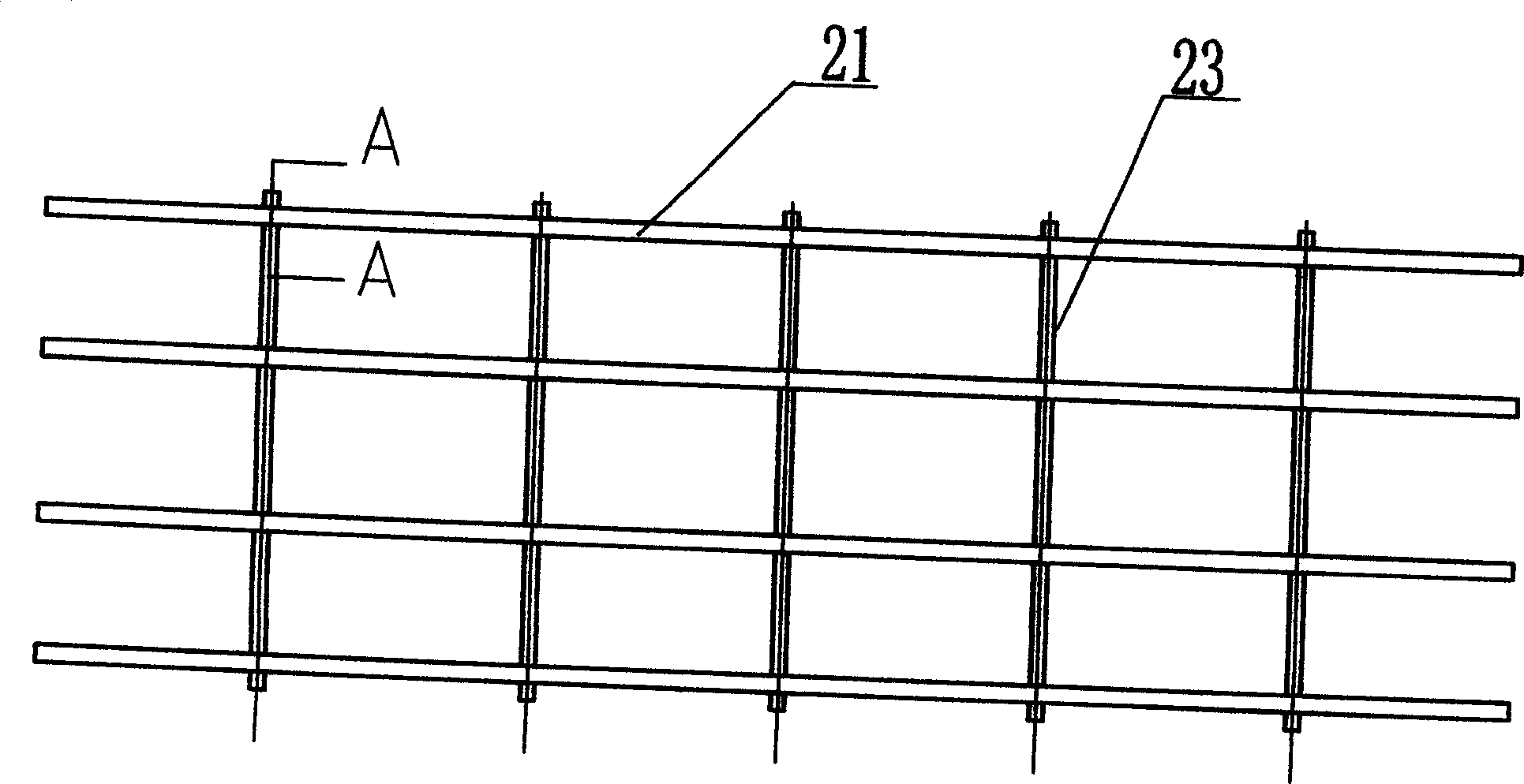
[0016] The floating energy-dissipating and noise-reducing device of the present invention is composed of a noise-reducing honeycomb panel 1, a supporting frame 2, a floating body 3 and a tightening hoop 4, and the supporting frame 2 is composed of several FRP I-shaped profiles 21, connecting rods 22 and the spacers 23 are equidistantly connected into a grid structure; the floating body 3 is a sealed tubular body, and the tubular floating body 3 is fixed below the support frame 2 by tightening the tie 4; the noise-reducing honeycomb panel 1. It is formed by splicing and bonding several pieces of PVC plastic molding boards 16. There are several special-shaped pipes with open ends on it. Each special-shaped pipe is provided with a vertical collection pipe 11 from top to bottom. Tube 12, curved surface energy dissipation tube 13, multi-stage energy dissipation groove 14 and diversion groove 15 are arranged on the curved surface energy dissipation tube 13; the cross-sectional shape ...


PUM


Abstract

The present invention relates to floating type energy-dissipating noise reduction equipment. It is formed from noise-reducing honeycomb plate, supporting skeleton and floating body. The noise-reducing honeycomb plate is placed on the supporting skeleton, the floating body is placed under the supporting skeleton, and the whole floating type energy-dissipating noise reduction equipment is placed in the water pool of cooling tower, and the distance of lower end of noise-reducing honeycomb plate from level of water pool is less than or equal to 200 mm. Besides, said invention also provides the concrete structures of noise-reducing honeycomb plate, supporting skeleton and floating body, and the concrete working principle of said energy-dissipating noise reduction equipment.

Description

technical field [0001] The invention relates to a falling water noise reducing device, in particular to a falling water noise reducing device in a cooling tower of a power plant. Background technique [0002] With the rapid development of the power industry and the continuous improvement of environmental protection requirements, the State Power Corporation has proposed specific noise indicators for newly-built cooling towers. The noise must meet the relevant national standards, and the construction of cooling towers without noise reduction facilities is not allowed. For existing cooling towers, noise reduction technical transformation must also be carried out within a time limit, otherwise production must be stopped for rectification, and the noise will not be accepted if it does not meet the standard. At present, most of the cooling towers in various power plants use fiber mesh noise reduction pads to reduce noise. Falling water directly hits the noise reduction pads. The n...

Claims


Application Information

Patent Timeline
Patent Type & Authority Applications(China)
IPC IPC(8): F28C1/10
Inventor 倪季良惠建本王增顺李罗中姜晓荣于龙庆
Owner 常州金坛塑料厂
Why Eureka
Try Eureka