Method and apparatus for detecting heat conducting pipe performance

A detection method and detection equipment technology, applied in the field of heat dissipation, can solve problems such as the inability to actually input heat into the heat pipe and detect the temperature difference at both ends, and achieve the effect of short test time

Inactive Publication Date: 2006-11-15
FU ZHUN PRECISION IND SHENZHEN +1
View PDF0 Cites 20 Cited by
  • Summary
  • Abstract
  • Description
  • Claims
  • Application Information

AI Technical Summary

Problems solved by technology

[0004] In order to solve the technical problem that the actual input heat and the temperature difference between the two ends of the heat pipe cannot be detected at the same time, it is necessary to provide a heat pipe performance detection method and detection equipment to simultaneously measure the actual heat input of the heat pipe and the temperature difference between the two ends. to test

Method used


Image

  • Method and apparatus for detecting heat conducting pipe performance
  • Method and apparatus for detecting heat conducting pipe performance
  • Method and apparatus for detecting heat conducting pipe performance

Examples


Embodiment Construction

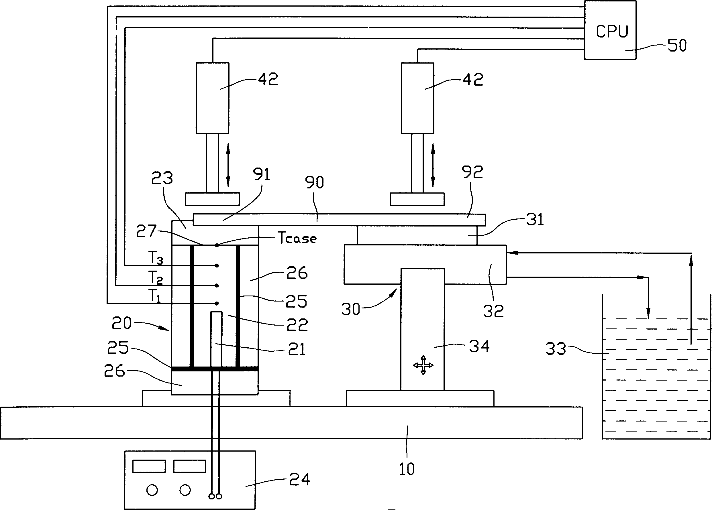
[0012] figure 2 Shown is a schematic diagram of the test principle of the performance test of the heat pipe according to the present invention, which mainly includes a bracket 10 and a test main part arranged on the bracket 10 . The main part of the test includes a heating device 20 and a cooling device 30 for simulating heating and cooling of the heat pipe 90, respectively, and a temperature measuring device (see below) for measuring temperature.

[0013] The heating device 20 includes an electric heating rod 21 , a heat conducting copper block 22 and a heating copper block 23 . The heat-conducting copper block 22 is a vertical column structure. The electric heating rod 21 is used as a heating source to heat the heat pipe 90. It is vertically placed in the same direction as the heat conduction copper block 22 and embedded in the middle of the lower half of the heat conduction copper block 22, and can be connected from a DC power supply. The heat is obtained at 24 and trans...


PUM


Abstract

The present invention discloses a method for detecting thermal pipe performance and its detection equipment. It includes a heating device and a cooling device. When the thermal pipe is detected, the evaporation section and condensation section of thermal pipe to be detected are respectively placed on said heating device and cooling device, then the heating device is used to heat said evaporation section to make the thermal pipe be reached to operation temperature, and the cooling device is used to cool the condensation section to make the thermal pipe be retained in working state, then it judges that the heat quantity inputted into evaporation section of said thermal pipe by heating device is greater than some defined value or not, if it is greater than some defined value, it can detect the temperature difference of two ends of said the thermal pipe and judge that said thermal pipe is qualified or not.

Description

【Technical field】 [0001] The invention relates to the field of heat dissipation, in particular to a heat pipe performance detection method and detection equipment. 【Background technique】 [0002] As a heat dissipation purpose, heat pipes are widely used in the fields of electronics, automobiles, aviation and chemical industry due to their fast heat transfer. The principle of absorbing or releasing a large amount of heat during liquid two-phase transformation works. The inner wall of the shell is usually provided with a capillary structure that facilitates the reflux of the condensed liquid to provide the driving force required for the accelerated reflux of the condensed liquid. When in use, one end of the heat pipe (the evaporation section) is placed at a high-temperature heat source, and the working fluid in the casing is heated and evaporated into a gaseous state. The steam flows through the cavity in the casing to the other end of the heat pipe (the condensation section) ...

Claims


Application Information

Patent Timeline
Patent Type & Authority Applications(China)
IPC IPC(8): G01N25/20G01M99/00G01N25/18
CPCF28D15/00F28F2200/005G01K1/026G01K13/00
Inventor 张长生林振辉黄登聪韩飞李震
Owner FU ZHUN PRECISION IND SHENZHEN
Why Eureka
Try Eureka