

Backlight module device based on polarization light source
A backlight module and light source technology, applied in optics, nonlinear optics, instruments, etc., can solve problems such as low light utilization efficiency
- Summary
- Abstract
- Description
- Claims
- Application Information
AI Technical Summary
Problems solved by technology
Method used
Image


Examples
Embodiment Construction
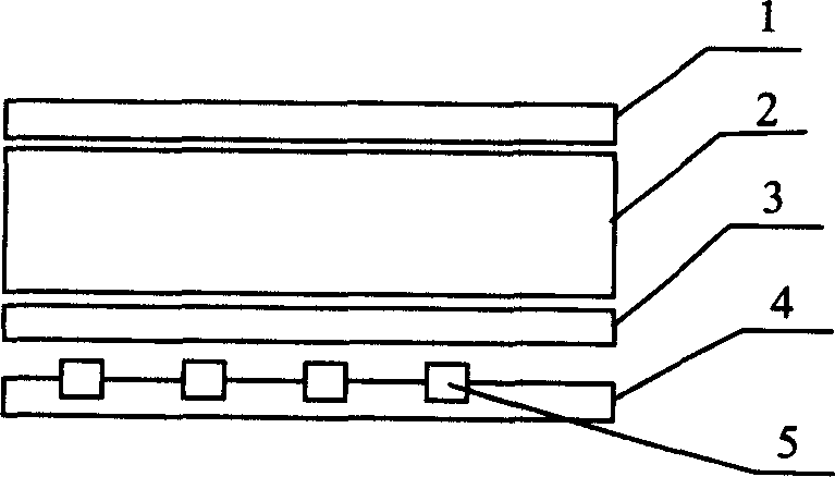
[0013] There are two types of backlight module devices based on polarized light sources provided by the present invention, that is, backlight module devices based on polarized light LEDs and polarized light OLEDs. The light source it adopts does not need a polarizer, and directly emits polarized light. details as follows:
[0014] 1. Backlight module device based on polarized LED
[0015] Its structure is as figure 1 As shown: it includes an optical film 3, a substrate 4 and a polarized LED 5, which are sequentially connected by an optical path. The polarized light source is a plurality of LEDs that directly emit polarized light. The number of LEDs is determined according to the brightness requirements and brightness uniformity. Different colors of polarized LEDs can be combined according to the backlight requirements to obtain the required color backlight. Polarized LEDs directly emit polarized light, and a plurality of polarized LEDs are attached to the substrate to obtai...
PUM
 Abstract
Description
Claims
Application Information