Axial flow fan and application method thereof

A technology of axial flow fan and rotating shaft, which is applied in the field of improved design of axial flow fan blade structure, which can solve the problems of increased air supply noise, noise, vortex generation, etc., and achieve the effect of low noise

Inactive Publication Date: 2006-11-22
HAIER GRP CORP +1
View PDF1 Cites 10 Cited by
  • Summary
  • Abstract
  • Description
  • Claims
  • Application Information

AI Technical Summary

Problems solved by technology

[0005] According to the reference document mentioned above, when the speed of the axial flow fan is increased to increase the air supply volume, since the expansion part is formed on the trailing edge of the blade, the air flowing out from this part will generate a vortex behind the expansion part, so the air supply noise will increase and become a noise problem in environments where air conditioners or ventilators are used

Method used


Image

  • Axial flow fan and application method thereof
  • Axial flow fan and application method thereof
  • Axial flow fan and application method thereof

Examples


Embodiment 1

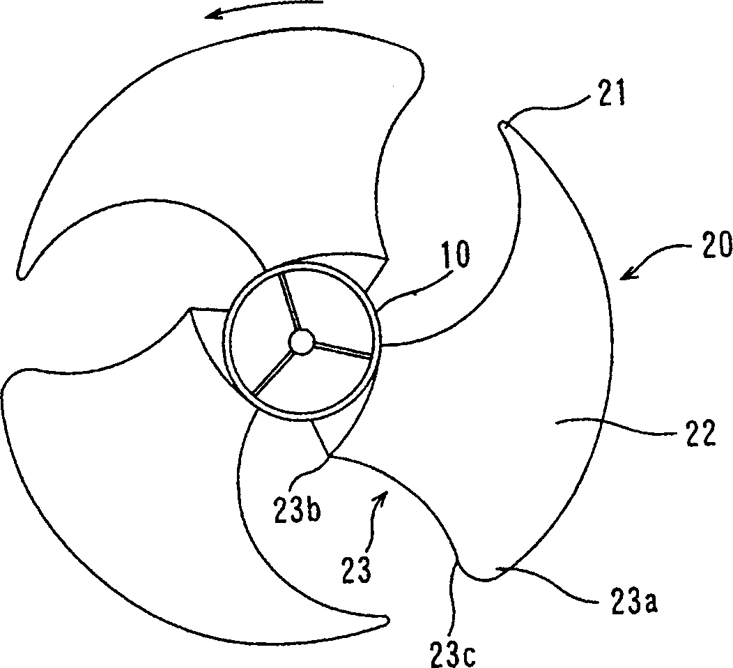
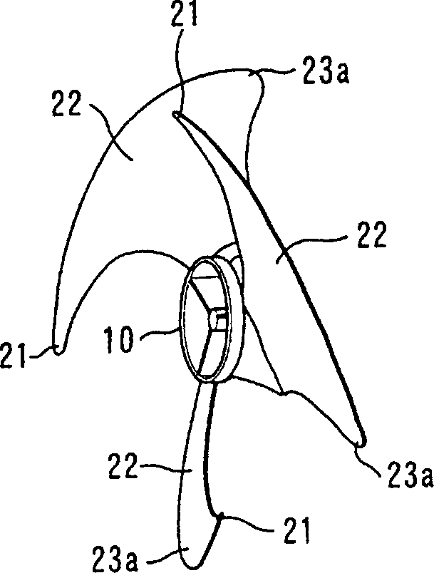
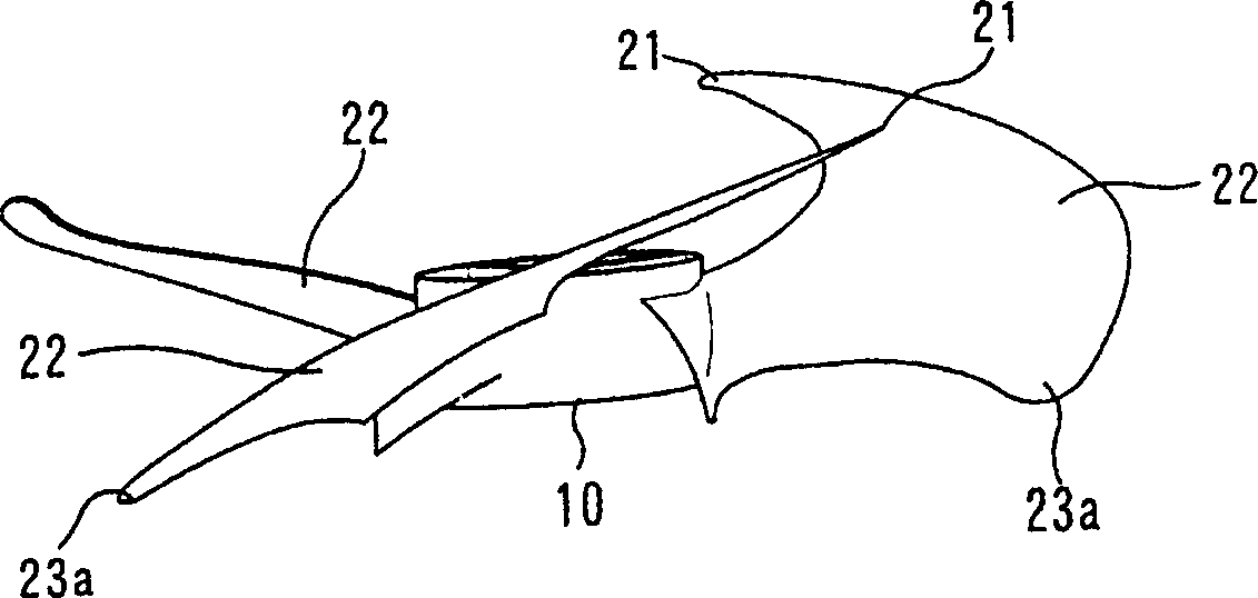
[0022] Example 1, such as Figure 1a to Figure 3b As shown, the axial flow fan of the present invention is composed of a hub 10 serving as a rotating shaft and three fins 20 arranged radially on its outer peripheral side, and the diameter of the fins 20 is 440 mm.

[0023] The method of applying the axial flow fan with the above structure is that the operating speed of the axial flow fan can be controlled within the range of 600 to 800 rpm.

[0024] As the axial flow fan with the above structure, its hub 10 is connected to the side of the rotating shaft of the motor, and according to Figure 1a The direction of the arrow shown is rotationally driven, whereby air flows in from the leading edge portion 21 on the front side in the direction of rotation of the blade 20, and after being pressurized by the airfoil surface 22, the air flows from the trailing edge on the front side in the direction of rotation of the blade 20. Part 23 is blown out.

[0025] The blade trailing edge po...


PUM

PropertyMeasurementUnit
Diameteraaaaaaaaaa

Abstract

The invention discloses an axial-flow fan and relative application, especially a new fan blade structure for reducing the fan noise, based on increasing wind amount, to meet the demands of air conditioner and improve the heat exchange efficiency. Wherein, said axial-flow fan comprises a central hub as the rotational axle and several wings radial arranged on the circumference of hub; the back edge of wing has an expansion part that liner expanding backwards the rotational speed of wing; said expanding part is formed by expanding from the inner edge at one side of hub to the outer edge, but not concave inwards to the rotational speed; the wing surface that facing the air-in side is a smooth plate; the diameter of said wing is between 400mm and 500mm; and its operation speed is controlled at 600-800rpm.

Description

technical field [0001] The invention relates to a novel axial flow fan and its application method for air conditioners and ventilators, in particular to the improved design of the vane structure of the axial flow fan. Background technique [0002] In outdoor units of air conditioners or other ventilation devices, various axial fans are usually used to realize air circulation. The basic structure of an existing axial flow fan is composed of a hub as a rotating shaft and several fins arranged radially on the outer peripheral side of the hub. Driven by the motor to rotate, air flows in from the leading edge of the blade, and is blown out from the trailing edge of the blade after the airfoil is boosted. [0003] At present, the structural improvement of the axial flow fan is mainly to increase the air supply volume and reduce the air supply noise. The improvement scheme is mainly for the air intake direction of the existing fins, the inclination direction, the inclination angl...

Claims


Application Information

Patent Timeline
IPC IPC(8): F04D19/00F04D27/00F04D29/38
Inventor 谷东照付裕王勇梁晓东管丽萍
Owner HAIER GRP CORP
Why Eureka
Try Eureka