High dynamic range compression method via adaptive exponential mapping

A technology of high dynamic range and compression method, which is applied in image data processing, instrumentation, calculation, etc., can solve the problems of large amount of calculation and poor global mapping effect, and achieve fast results

Inactive Publication Date: 2006-11-22
PEKING UNIV
View PDF0 Cites 10 Cited by
  • Summary
  • Abstract
  • Description
  • Claims
  • Application Information

AI Technical Summary

Problems solved by technology

[0006] The effect of the early global mapping method is not as good as the local mapping method, the literature "Adaptive LogarithmicMapping For displaying High Contrast Scenes" (Drago F., Myszkowski K., Annen T., and Chiba N, EUROGRAPHICS2003.Vol.22, No.3, 419- 426) Using the logarithmic law B=k describing the response of the human eye to the actual scene luminosity L in the human visual system 1 ln(L / L 0 ), where L 0 is the background luminosity, k 1 As a constant, the bias function is introduced to adaptively change the base of the logarithm, realizing a fast and high-quality dynamic range compression method, which achieves a similar effect to the local mapping method, but it needs to calculate the bias function for each pixel, The amount of calculation is still large

Method used


Image

  • High dynamic range compression method via adaptive exponential mapping
  • High dynamic range compression method via adaptive exponential mapping
  • High dynamic range compression method via adaptive exponential mapping

Examples


Embodiment Construction

[0022] DETAILED DESCRIPTION OF THE PREFERRED EMBODIMENTS The preferred embodiments of the present invention will be described in more detail below with reference to the accompanying drawings of the present invention.

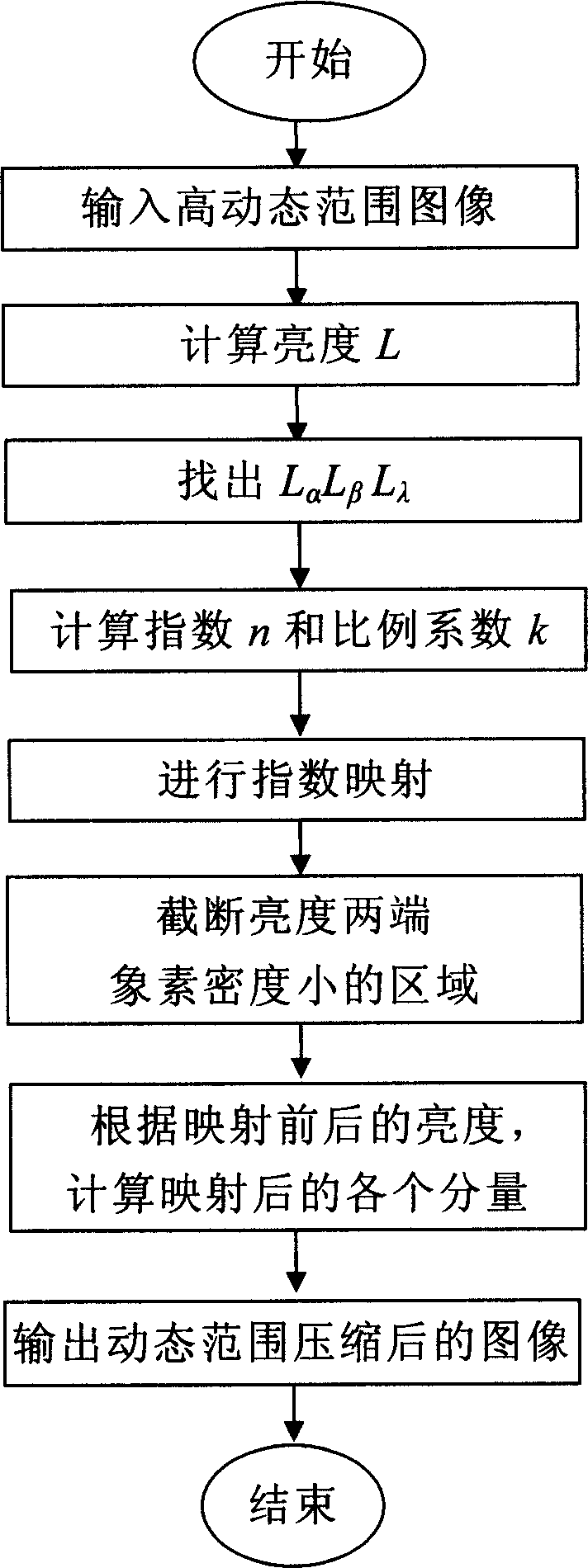
[0023] figure 1 The flow chart of adaptive exponential mapping high dynamic range compression of the present invention is given, mainly including the following steps:

[0024] 1) According to each channel of the input high dynamic range image, calculate its brightness L, the calculation formula is L=0.299×R+0.587×G+0.114×B, R, G, B are the three color high dynamic range images portion.

[0025] 2) find L α L β L λ , where L x is the brightness of the high dynamic range image, the brightness is less than L x The ratio of the number of pixels to the total number of pixels is x, where x represents α, β, and λ, and its values ​​are given by the user. Generally, α=0.002, β=0.98, and γ=0.1 can be taken. We divide the brightness range of the image into 10,000 pa...


PUM


Abstract

The related compressing method for image with dynamic range comprises: compressing the image with adaptive index mapping to reserve details, cutting off the end area with small pixel density to reserve contrast, and calculating color weight after compressing. Compared with prior art, this invention improves speed and fit to full auto or manual operation.

Description

technical field [0001] The invention belongs to the technical field of image expression in digital image processing, and in particular relates to the dynamic range compression technology of high dynamic range images. Background technique [0002] In recent years, high dynamic range (High Dynamic Range, HDR) images have begun to have more and more applications in fields such as computer graphics and virtual reality. The ratio of the maximum brightness to the minimum brightness of a pixel in an image is called the dynamic range of the image. Traditional 24-bit RGB images use 8-bit integers to represent each color component, so their dynamic range is only 100:1, while the dynamic range of actual scenes can be as high as 100,000,000:1, which is far beyond the expression range of 24-bit RGB images. High dynamic range images use real numbers to represent each color component of the image, not only can fully express the dynamic range of the actual scene, but also the brightness va...

Claims


Application Information

Patent Timeline
Patent Type & Authority Applications(China)
IPC IPC(8): G06T9/00
Inventor 章卫祥安维华周秉锋
Owner PEKING UNIV
Why Eureka
Try Eureka