Structural damage index mapping system and method

a structural damage and index mapping technology, applied in the field of structural damage index mapping system and method, can solve the problems of large industry and consumer costs, large labor and time consumption of installing each sensor one-by-one, and large sensor wiring complexity, so as to eliminate small islands, eliminate small holes, and smooth image contours

Inactive Publication Date: 2014-09-09
HONEYWELL INT INC
View PDF20 Cites 9 Cited by
  • Summary
  • Abstract
  • Description
  • Claims
  • Application Information

AI Technical Summary

Problems solved by technology

This is because, among other things, the structural integrity of systems and components in the aerospace industry can possibly cause in-flight shutdowns, take-off aborts, delays, or cancellations, all of which can result in significant industry and consumer costs.
For example, installing each of the sensors one-by-one can be both labor-intensive and time-consuming When the sensors are implemented as phase arrays, which can be very sensitive to inaccuracies in the sensor placement, it may be necessary to assure the precise position of each of the sensors.
Moreover, the sensor wiring can be relatively complicated, and the length, volume, and weight of the sensor wiring can be significant.
The presently known CT methods can provide relatively precise defect images, but can also be relatively time-consuming and computationally intensive.
As a result, the CT methods may not be useful when real-time structural health monitoring is desired, because sparse sensor arrays are generally used for such applications.
For relatively complex structures, indentifying a wave reflected by a defect can be extremely challenging due to the presence of various structural elements such as stringers, stiffeners, borders, holes, rivets, bolts, etc., which can be sources of background reflections.
However, the RAPID algorithm exhibits several drawbacks of its own.
Moreover, images that are generated based on the RAPID algorithm can include false artifacts if certain parameters are not set optimally.
These false artifacts may also be generated due to the non-uniform coverage provided by the network of direct paths between sensor / actuator pairs.
Namely, a system and method that does not rely on the precise positioning of individual sensors and / or relatively complicated, long, voluminous, and heavy sensor wiring and / or is relatively insensitive to phase synchronization between the baseline and actual signals and / or does not generate images that include false artifacts if certain parameters are not set optimally.

Method used


Image

  • Structural damage index mapping system and method
  • Structural damage index mapping system and method
  • Structural damage index mapping system and method

Examples


Embodiment Construction

[0025]The following detailed description is merely exemplary in nature and is not intended to limit the invention or the application and uses of the invention. As used herein, the word “exemplary” means “serving as an example, instance, or illustration.” Thus, any embodiment described herein as “exemplary” is not necessarily to be construed as preferred or advantageous over other embodiments. All of the embodiments described herein are exemplary embodiments provided to enable persons skilled in the art to make or use the invention and not to limit the scope of the invention which is defined by the claims. Furthermore, there is no intention to be bound by any expressed or implied theory presented in the preceding technical field, background, brief summary, or the following detailed description.

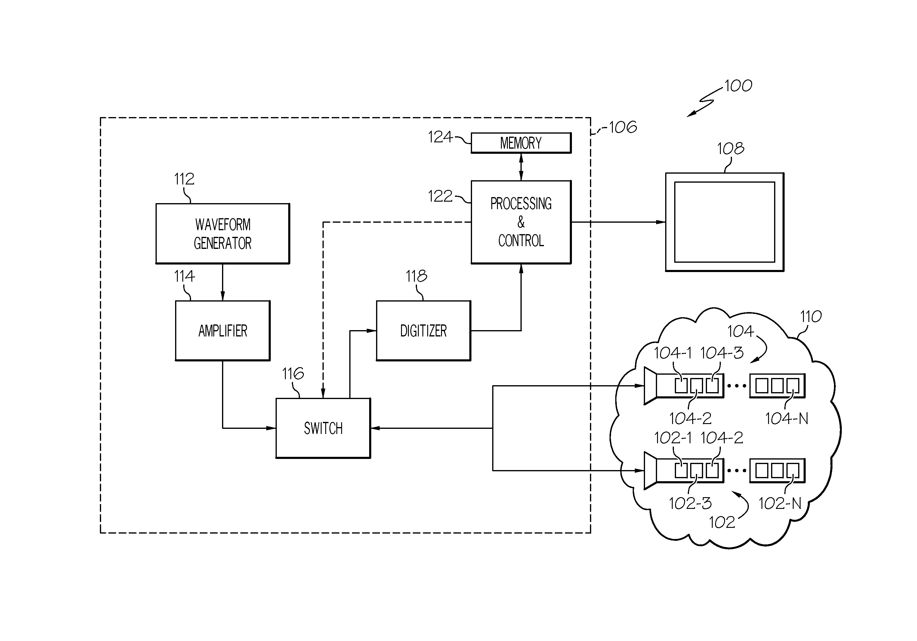
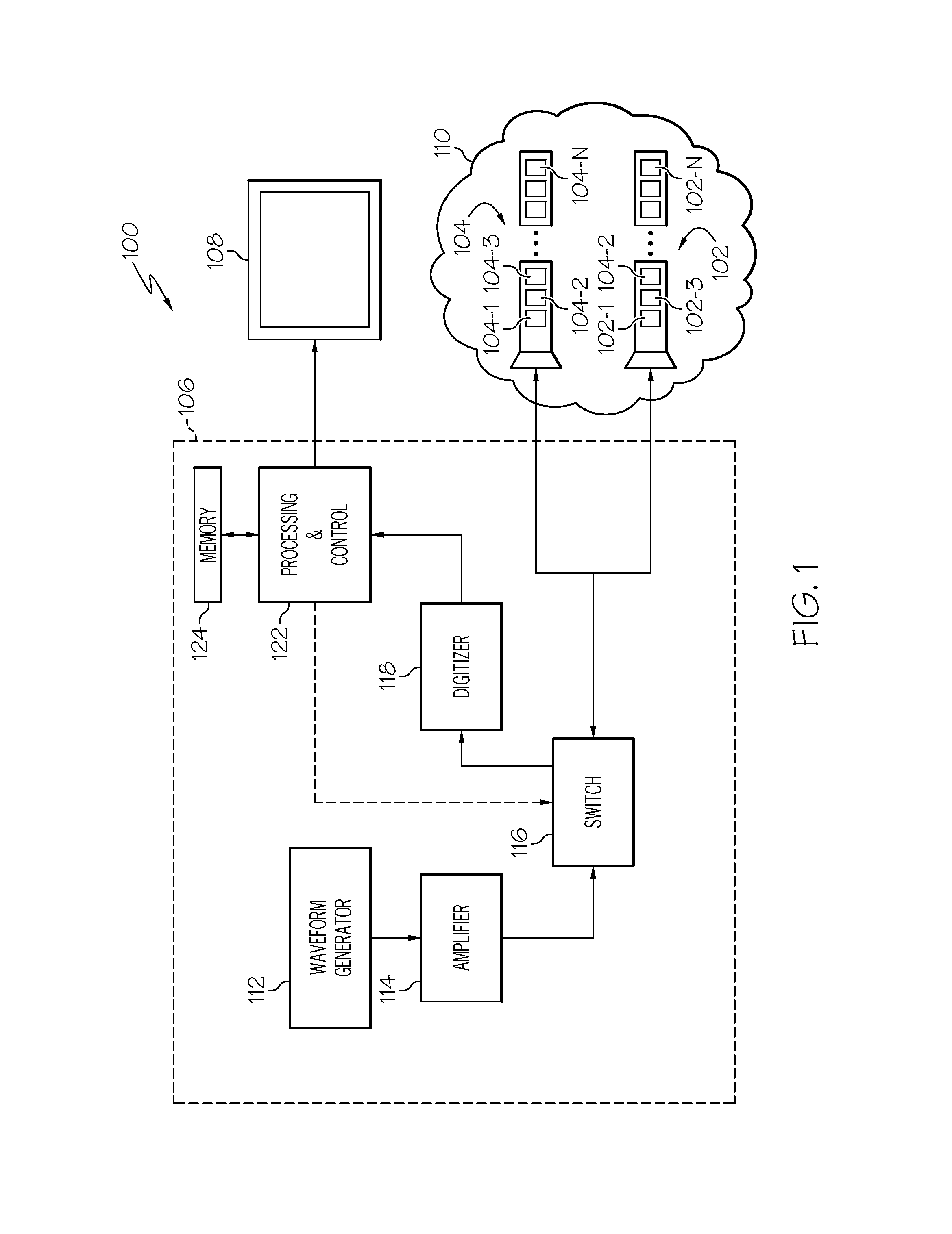
[0026]Referring first to FIG. 1, a functional block diagram of one embodiment of a structural defect detection and evaluation system is depicted. The depicted system 100 includes a plurality of...


PUM

PropertyMeasurementUnit
structural defectsaaaaaaaaaa
structural defect detectionaaaaaaaaaa
flexibleaaaaaaaaaa

Abstract

A system and method for detecting and evaluating structural defects are provided. Baseline data representative of sensed ultrasonic waves that were transmitting into a structure with no defects are stored. Ultrasonic waves are transmitted into the structure from a plurality of actuators that are coupled to the structure. The ultrasonic waves that are transmitted into the structure from the plurality of actuators are sensed, with a plurality of sensors that are coupled to the structure and spaced apart from the actuators, to thereby generate and supply sensor data. Signal difference coefficients are calculated from the baseline data and the sensor data. The calculated signal difference coefficients are spatially mapped to detect one or more structural defects in the structure.

Description

TECHNICAL FIELD[0001]The present invention generally relates to structural health monitoring, and more particularly relates to a system and method for detecting, localizing, and evaluating the size of structural defects.BACKGROUND[0002]Structural health monitoring is becoming of ever-increasing significance for many industries. One industry for which this is becoming especially significant is the aerospace industry. This is because, among other things, the structural integrity of systems and components in the aerospace industry can possibly cause in-flight shutdowns, take-off aborts, delays, or cancellations, all of which can result in significant industry and consumer costs.[0003]Some presently known structural health monitoring systems use arrays of various sensors. The use of such arrays, which can range from tens to hundreds of sensors, exhibits certain drawbacks. For example, installing each of the sensors one-by-one can be both labor-intensive and time-consuming When the senso...

Claims


Application Information

Patent Timeline
Patent Type & Authority Patents(United States)
IPC IPC(8): G06F19/00G01N29/04G01N29/06G01N29/07G01N29/44
CPCG01N29/043G01N29/069G01N29/07G01N29/4427G01N2291/0258G01N2291/105G01N29/0645G01N29/245G01N29/4436G01N2291/106
Inventor HEDL, RADEKFINDA, JINDRICHADAMEK, KAREL
Owner HONEYWELL INT INC
Why Eureka
Try Eureka