Electric connector manufacturing method

A technology of an electrical connector and a manufacturing method, which is applied to the manufacturing field of electrical connectors, can solve the problems of low manufacturing efficiency, complex molds, difficulties, etc., and achieve the effects of enhanced holding force, high manufacturing efficiency and low cost.

Inactive Publication Date: 2006-11-22
FOXCONN (KUNSHAN) COMPUTER CONNECTOR CO LTD +1
View PDF0 Cites 2 Cited by
  • Summary
  • Abstract
  • Description
  • Claims
  • Application Information

AI Technical Summary

Problems solved by technology

[0003] The above methods have their own shortcomings. With the development of electrical connectors in the direction of miniature, high speed and stability, the insulating body and conductive terminals of electrical connectors are also developing in the direction of miniature and high density. If the first method is adopted , the barb and the terminal are in a horizontal sheet shape, and the contact area with the inner wall of the insulating body is very small, that is, the interference between the two is small, and it is difficult to ensure effective retention in the insulating body when the terminal is docked many times or subjected to other strong impacts. Inside the main body; if the second method is adopted, due to the small size of the electrical connector, the mold for manufacturing the insulating body is generally more complicated, and making the wall of the terminal accommodating cavity into a curved surface will inevitably affect the structure of the insulating body, making the manufacturing of the insulating body difficult. In addition, it is difficult to bend the small-sized conductive terminal into an arc surface, which is not conducive to simplifying the manufacturing process and will increase the cost of manufacturing the connector; if the third method is used, an additional The terminal holder used to hold the terminal is not only low in manufacturing efficiency, but also relatively ineffective in cost

Method used


Image

  • Electric connector manufacturing method
  • Electric connector manufacturing method
  • Electric connector manufacturing method

Examples


Embodiment Construction

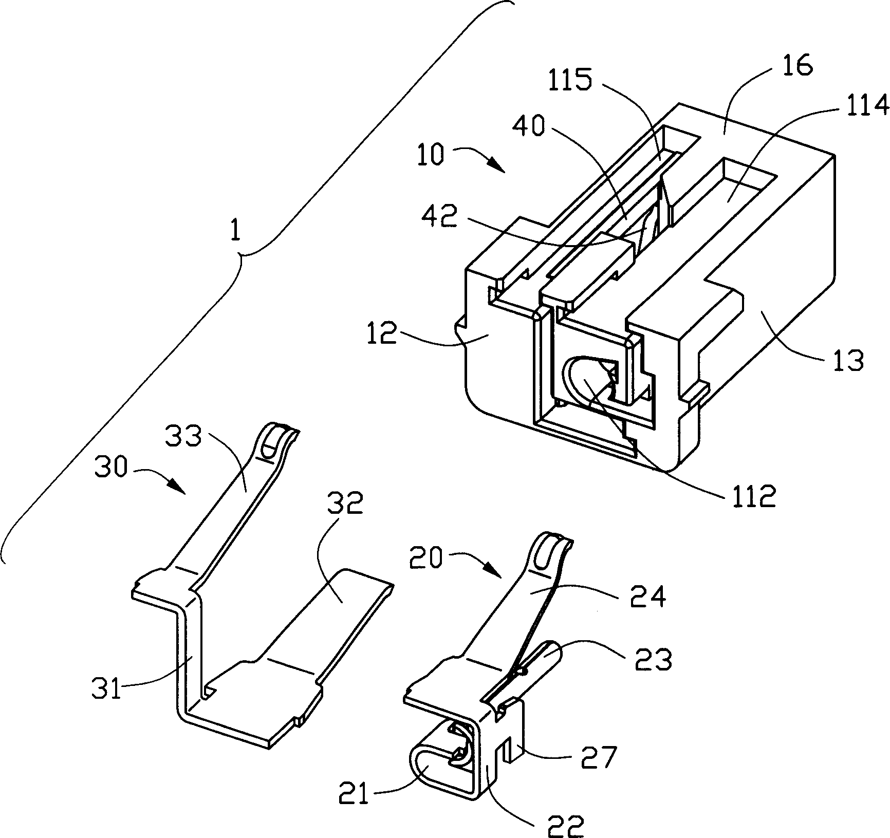
[0014] see Image 6 As shown, the manufacturing method of the electrical connector of the present invention can be completed through the following steps, including the step of forming an insulating body; the step of forming a plurality of conductive terminals; the step of assembling the conductive terminals into the insulating body to complete the semi-finished electrical connector; The step where the connector is molded again to complete the finished electrical connector.

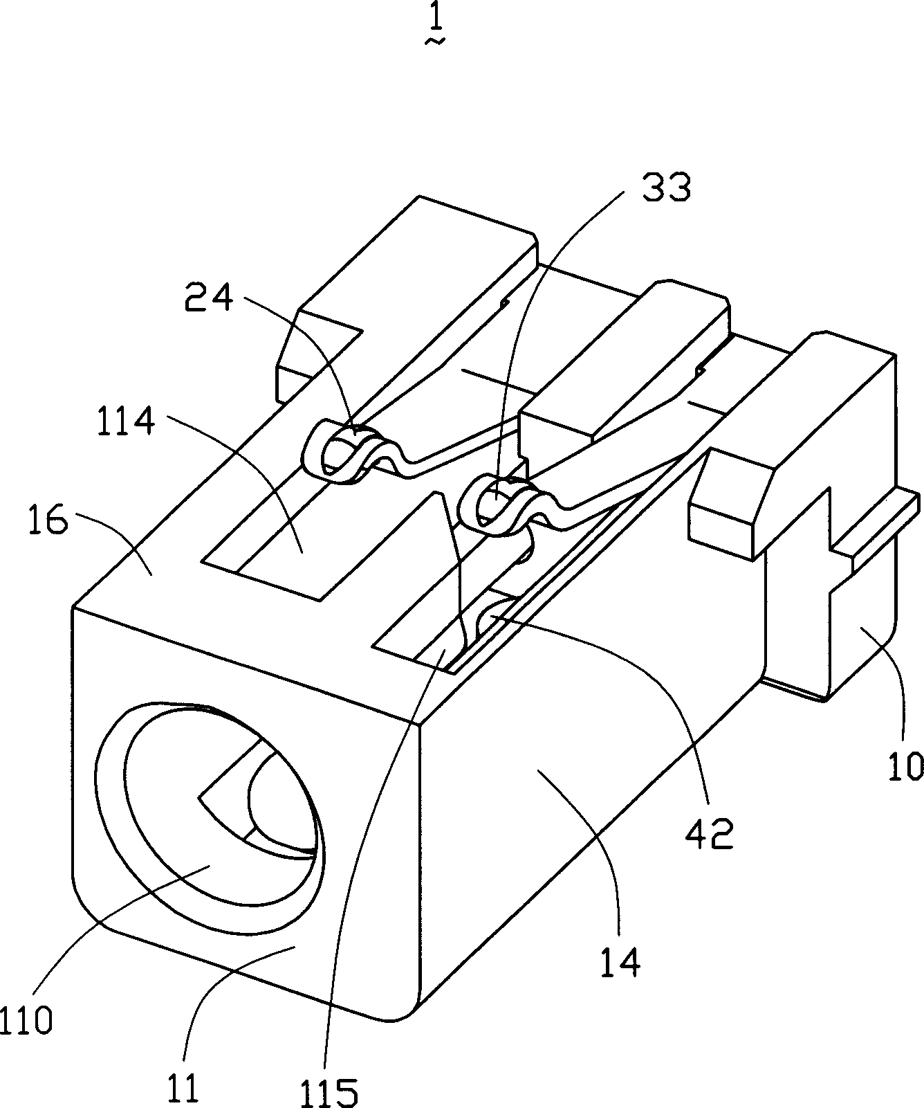
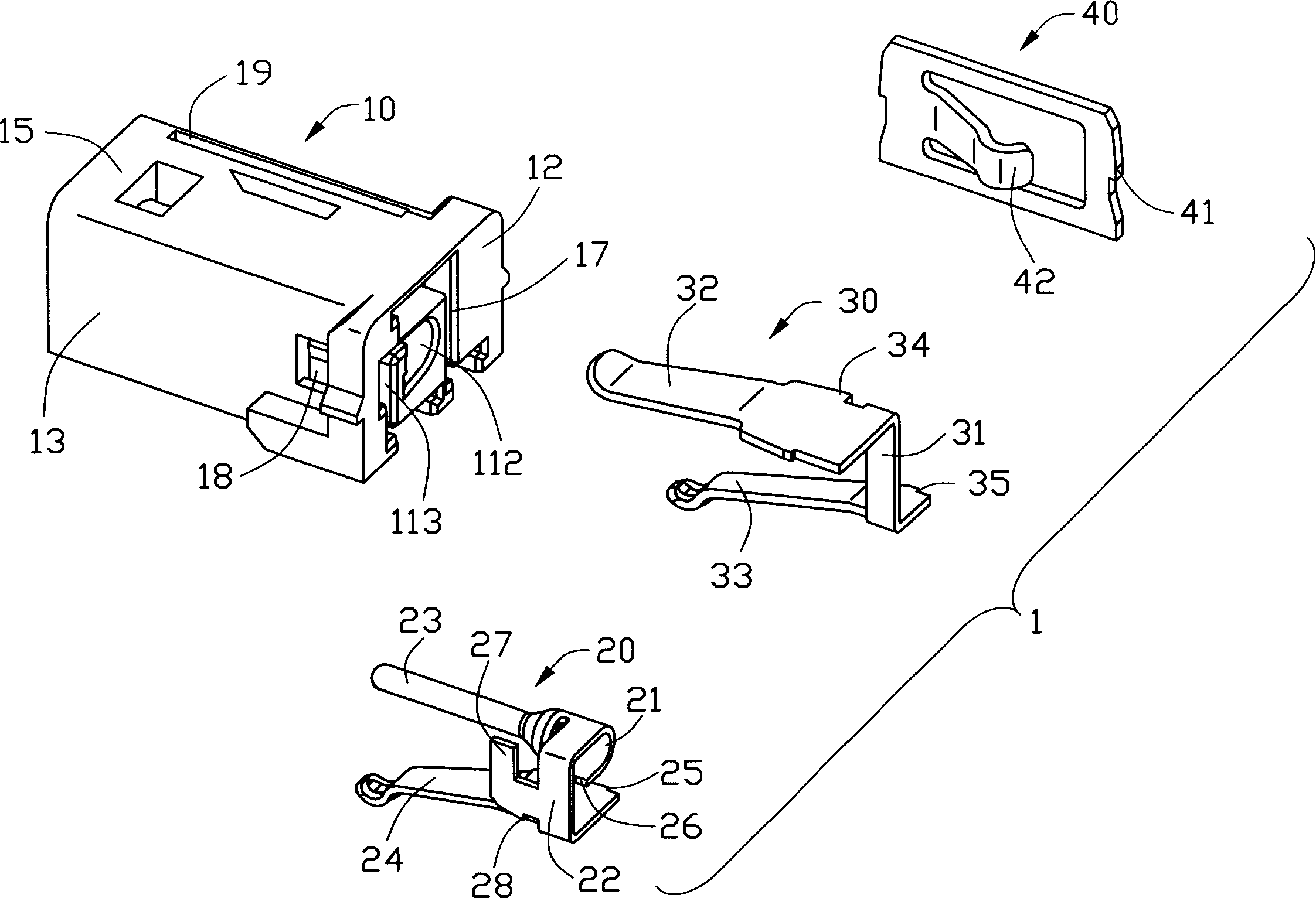
[0015] The step of forming the insulating body is completed by injection molding technology, injecting molten insulating body material, in this embodiment, molten plastic (not shown) into the cavity of the mold for forming the insulating body through a gate (not shown) , see figure 1 , figure 2 As shown, the formed insulating body 10 is in a longitudinal configuration, including a front end surface 11, a rear end surface 12 opposite to the front end surface 11, a first side surface 13 connecting the fro...


PUM


Abstract

The invention discloses a preparing method of electric connector, which comprises the following steps: moulding front end surface, back end surface and lateral insulating bulk between front and back end surfaces; setting through-hole to insides of terminal hole on the lateral; moulding several conductive terminals with base; fixing terminal in the holding part of terminal in the hole; setting joint plate on base lateral; loading terminal group in the insulating bulk to make terminal holding part in the terminal hole to form semi-product electric connector; exposing joint plate in the through-hole when conductive terminal is put in the terminal hole; moulding semi-conductor electric connector again to form product; inserting inward bending connector in the insulating bulk by piercing through-hole to punch joint plate.

Description

【Technical field】 [0001] The invention relates to a manufacturing method of an electrical connector, and mainly relates to a manufacturing method of the electrical connector capable of strengthening the holding force between the terminals of the electrical connector and the insulating body. 【Background technique】 [0002] The electrical connector generally includes an insulating body with a plurality of terminal receiving cavities and a plurality of conductive terminals accommodated in the receiving cavities. Usually, due to the consideration that the terminals need to be easily inserted into the corresponding terminal receiving cavities, the receiving cavities are mostly flat and parallel and elongated. Correspondingly, the terminals are also flat sheet and elongated, and can be The shaft is inserted into the receiving cavity. Generally, there are several ways to hold the terminal in the storage cavity: 1. Set barbs on both sides of the flat sheet terminal, and hold the te...

Claims


Application Information

Patent Timeline
Patent Type & Authority Applications(China)
IPC IPC(8): H01R24/58H01R43/16H01R43/18
CPCH01R24/64
Inventor 钟永谦陈坤华
Owner FOXCONN (KUNSHAN) COMPUTER CONNECTOR CO LTD
Why Eureka
Try Eureka