Tube coupling

a technology of coupling and tube, which is applied in the direction of couplings, hose connections, rod connections, etc., can solve the problems of the gripper ring teeth going into the groove of the tubing, and achieve the effect of increasing the ultimate increasing the holding power of the rings

Inactive Publication Date: 2005-08-25
ACCOR TECH
View PDF3 Cites 1 Cited by
  • Summary
  • Abstract
  • Description
  • Claims
  • Application Information

AI Technical Summary

Benefits of technology

[0005] It is a first improvement of the invention to reverse the position of a gripper ring in the coupling from the position shown in the U.S. Pat. No. 4,911,406. In the embodiments of this invention, the seal, such as an O-ring seal, is arranged axially inward of the gripper ring in the outer housing of the coupling. This is followed by a spacer bushing which holds the ring in place and the gripper ring, with its teeth, is on the axially outer side of the spacer bushing. This enables the detection of a leak caused by inadequately inserting a tube into the O-ring seal. It is particularly advantageous also in the situation of re-piping or replacing a previous metal valve to enable the existing compression ring used with metal vales to fit into a valve using this gripper ring arrangement.
[0006] It is a second improvement of the invention of U.S. Pat. No. 4,911,406, to provide two or more gripper rings for increasing the holding power of the rings in the coupling for use with the softer tubing. The two or more gripper rings co-act on the tubing in a synergistic effect distributing the load between them to substantially increase the holding power of the rings in the softer tubing. It is believed that the softness of the tubing allows movement of the teeth in the plastic until the load on the rings is distributed over more of the rings thus increasing the ultimate holding power of the rings.

Problems solved by technology

The softer tubing material can cause the teeth of the gripper ring to gouge grooves in the tubing when the tubing is subjected to high numbers of repeated cycles at higher hydrostatic pressures.

Method used


Image

  • Tube coupling
  • Tube coupling
  • Tube coupling

Examples


Embodiment Construction

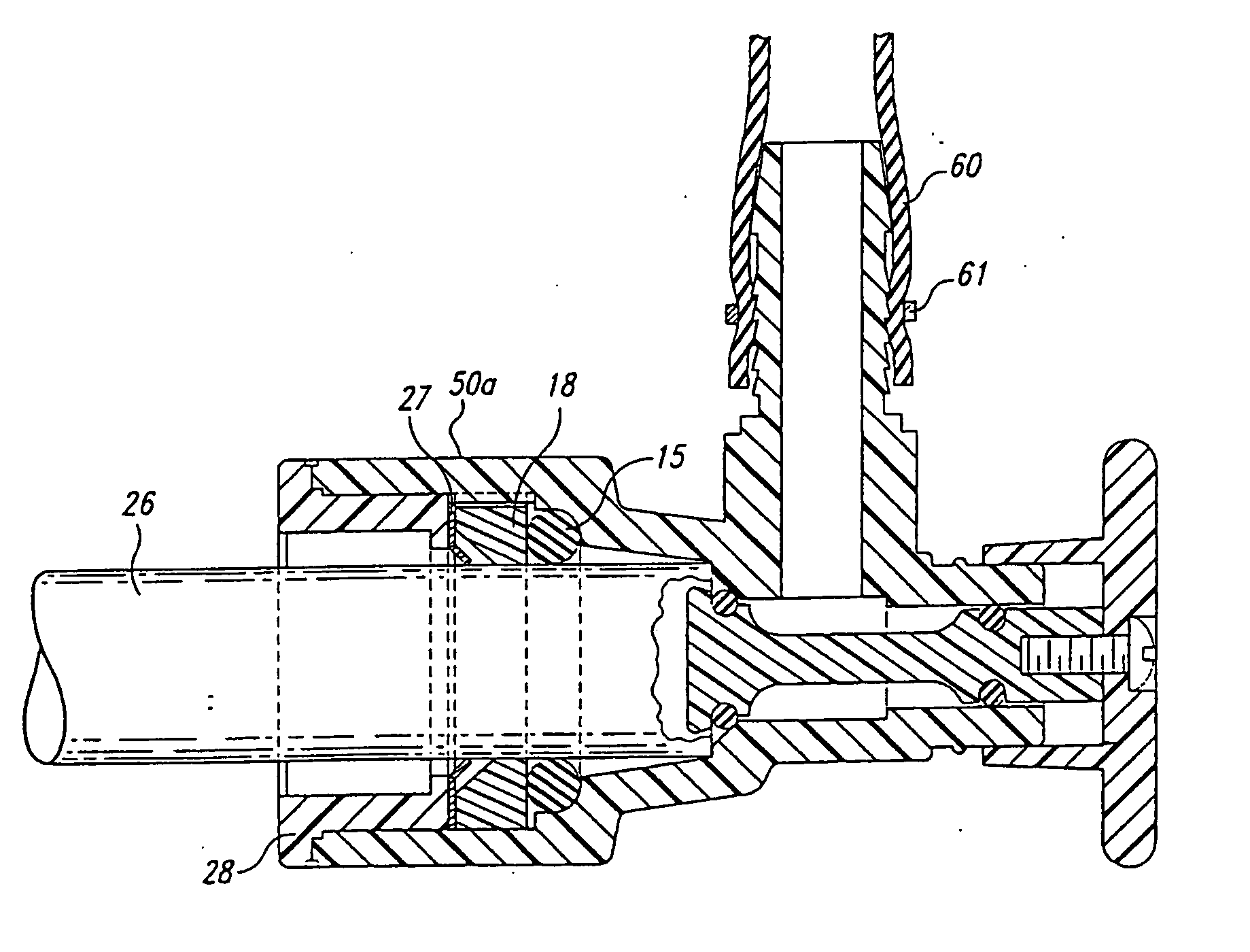
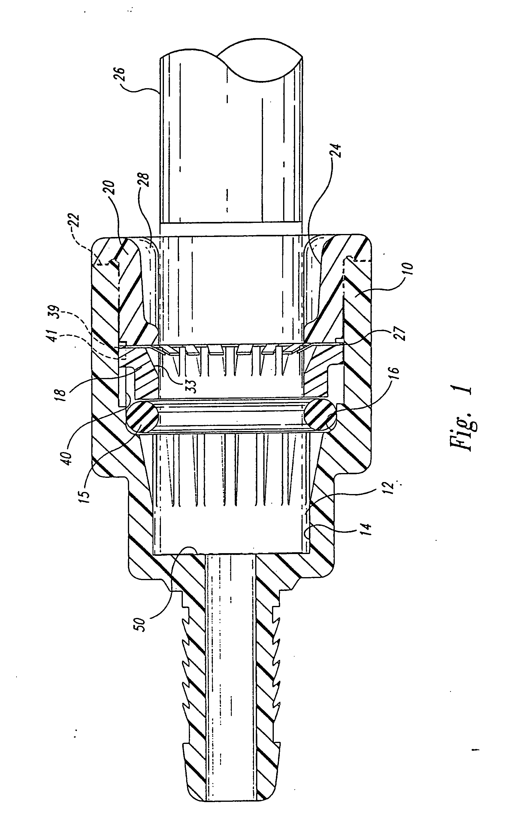
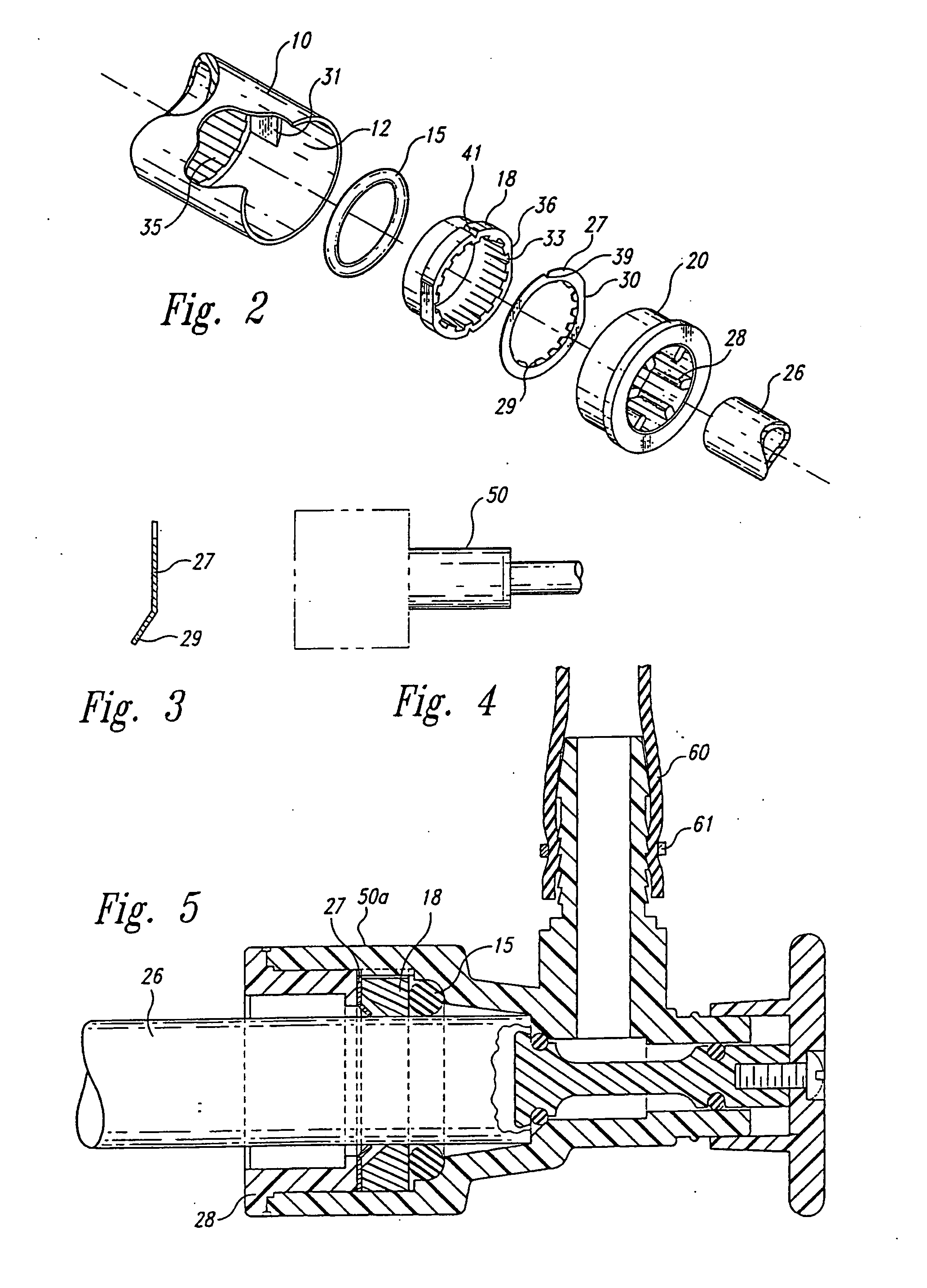
[0020] As best shown in FIG. 1, the unique coupling is shown in one form as a generic coupling but could be a test cap. A test cap, for example, is used in the plumbing industry for checking temporarily on the pressure of a plumbing system to see if all of the joints are free from leaks and that the proper pressure may be maintained. Usually then the test cap is removed and a permanent valve soldered or bonded onto the tube. The many applications for the coupling is further shown generically in phantom lines in FIG. 4, in which the phantom line box is a test cap coupling, a valve, an end unit like a shower-head, a coupling for joining two pieces of tubing together, etc. FIG. 5 shows more specifically the invention for the valve. The details of these different applications are obvious to one of ordinary skill in the art and the details of U.S. Pat. No. 4,911,406 are incorporated herein by reference thereto.

[0021] In all of the couplings of FIGS. 1-5, the invention includes an outer ...


PUM

PropertyMeasurementUnit
thicknessaaaaaaaaaa
thicknessaaaaaaaaaa
pressureaaaaaaaaaa

Abstract

A fluid coupling having an outer housing with an internal bore, an O-ring fitted within the bore, a spacer bushing fitted against the O-ring, a gripper ring fitted against the axially outer side of the spacer ring, the gripper ring having axially and radially inwardly protruding circumferentially spaced gripping teeth, the teeth arranged for providing a twist when subjected to simultaneous rearward axial and rotational forces, and an end bushing holding the gripper ring, spacer bushing, and O-ring within the outer housing. A fluid coupling having an outer housing with an internal bore, an O-ring seal fitted within the bore, a spacer bushing fitted against the seal, a first gripper ring fitted against the axially outer side of the spacer ring, a second gripper ring fitted against the O-ring seal, the gripper rings having axially and radially inwardly protruding circumferentially spaced gripping teeth, in one embodiment the teeth arranged for providing a twist when subjected to simultaneous rearward axial and rotational forces, and an end bushing holding the gripper rings, spacer bushing, and O-ring within the outer housing.

Description

CROSS-REFERENCES TO RELATED APPLICATIONS [0001] This application is a continuation of U.S. patent application Ser. No. 10 / 266,935, filed Oct. 7, 2002; which is a continuation of U.S. patent application Ser. No. 09 / 570,846, filed May 12, 2000, now U.S. Pat. No. 6,464,266; which is a continuation-in-part of U.S. patent application Ser. No. 09 / 216,376, filed Dec. 18, 1998, now abandoned, and a continuation-in-part of U.S. patent application Ser. No. 09 / 425,909, filed Oct. 21, 1999, now abandoned, and claims the benefit of PCT / US99 / 30149, filed Dec. 17, 1999, which applications are incorporated herein by reference in their entirety.TECHNICAL FIELD [0002] This invention pertains to removable couplings of the type for securing a plastic or copper tube by pressing on the tube without the need for welding or solder. BACKGROUND OF THE INVENTION [0003] U.S. Pat. No. 4,911,406 shows a tube coupling in which a metal or plastic tube can be coupled in a fluid-tight connection to a valve or the li...

Claims


Application Information

Patent Timeline
Patent Type & Authority Applications(United States)
IPC IPC(8): B29C65/08B23P21/00F16B7/20F16B7/22F16L37/092F16L37/12F16L47/06
CPCB29C65/08B29C66/52296B29C66/52297B29C66/534B29C66/5344F16L37/088F16L37/091B29C66/52292B29C66/52298F16K1/12B29C66/71B29C66/1122B29K2023/0691B29K2023/18B29K2027/06F16L37/084
Inventor O'NEILL, JERRY E.WHITNEY, CHARLIE
Owner ACCOR TECH
Why Eureka
Try Eureka