User operating blocking-up device

A user and input device technology, applied in the direction of measuring device, instrument, data processing power supply, etc., can solve the problems of high cost, high power consumption, complicated circuit, etc., and achieve the effect of cost saving, simple circuit design, and power saving.

Inactive Publication Date: 2006-11-29
MITAC COMP (SHUN DE) LTD +1
View PDF0 Cites 5 Cited by
  • Summary
  • Abstract
  • Description
  • Claims
  • Application Information

AI Technical Summary

Problems solved by technology

[0005] But using another independent microprocessor and fuel gauge, not only the circuit is more complicated, but also the cost is higher, and the power consumption is also high, so it must continue to be improved

Method used


Image

  • User operating blocking-up device
  • User operating blocking-up device

Examples


Embodiment Construction

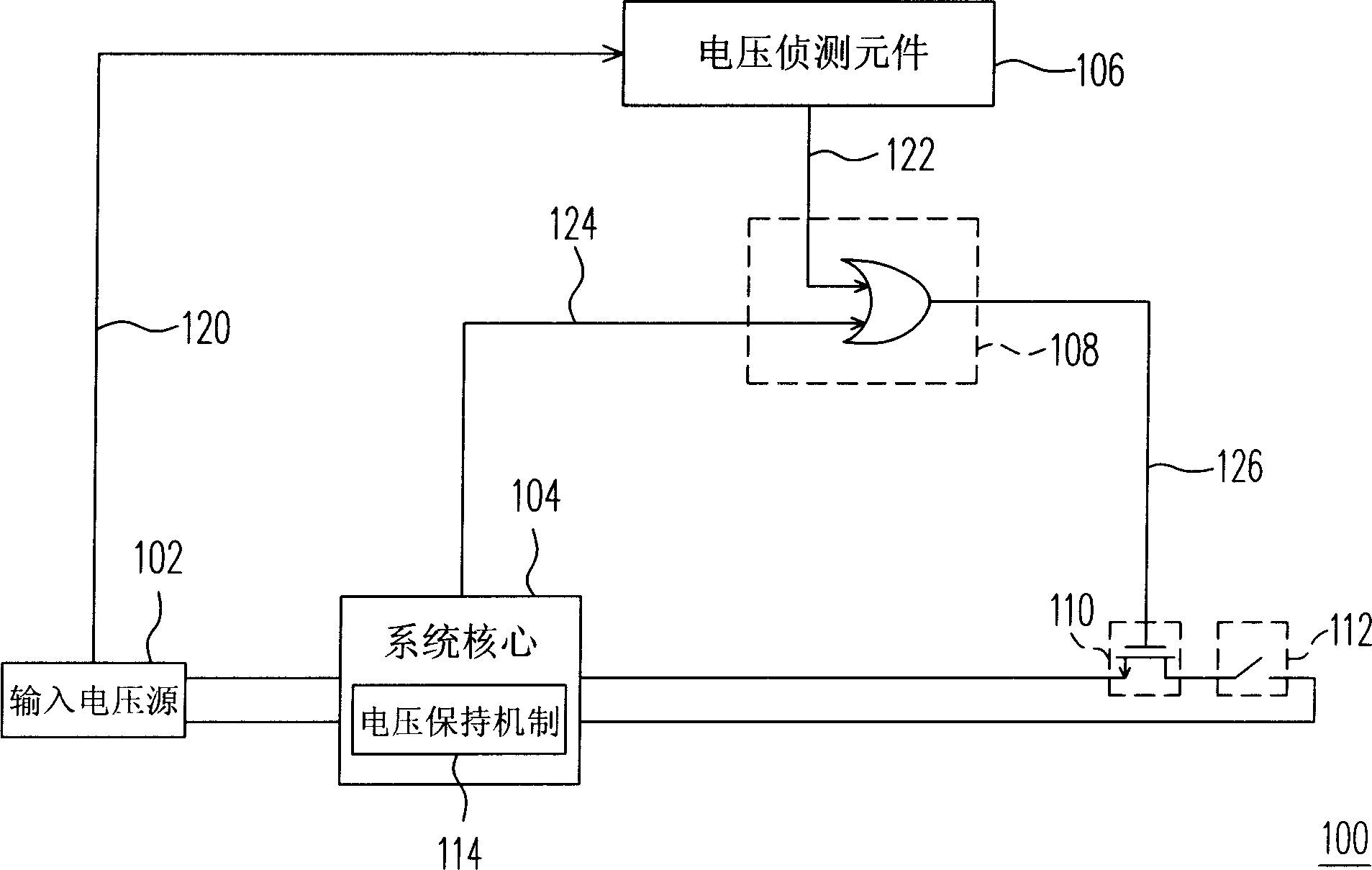
[0011] Please refer to figure 1 , the user operation blocking device 100 includes a voltage detection element 106 , a logic element 108 , and a switch element 110 .

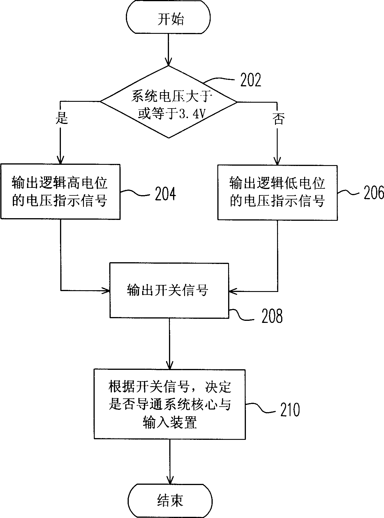
[0012] The voltage detection element 106 is electrically coupled to the input voltage source 102 to receive the system voltage 120 output by the input voltage source 102 , and output a voltage indication signal 122 to the logic element 108 according to the system voltage 120 . In this embodiment, when the system voltage 120 is greater than or equal to the first preset voltage, the voltage detection element 106 will output a logic high voltage indication signal 122, and when the system voltage 120 is lower than the first preset voltage, the voltage The detection element 106 outputs a voltage indicating signal 122 of logic low level. In this embodiment, the first preset voltage is about 3.4 volts.

[0013] The logic element 108 receives the voltage indication signal 122 output by the voltage detection element 106...


PUM


Abstract

This invention relates to a device for stopping operations of users including a voltage detection unit, a logic unit and a switch unit, in which, the voltage detecting unit is coupled to an input voltage source to output voltage instruction signals based on the systematic voltages provided by the input voltage source, the logic element outputs a switch signal based on the voltage instruction signal and the system mode signal output by the core, the switch element decides if it conducts the core and the input device based on the switch signal output by the logic element.

Description

【Technical field】 [0001] The present invention relates to a user-operated blocking device, and in particular to a user-operated blocking device for protecting a system when the voltage is insufficient. 【Background technique】 [0002] In today's general electronic devices, when the central processing unit or microprocessor detects that the voltage of the power supply or the battery is too low, it usually commands the system to enter a sleep mode to save power. In addition, devices that have entered sleep mode will also face insufficient voltage after a long period of standby. [0003] When the system is already in sleep mode and the voltage of the power supply is too low, when the user wakes up the system through any actions such as buttons, switches, and cards, because the system voltage is too low, it may occur when the system is activated or after activation. Soon, a system failure or data loss occurred. [0004] In order to solve the above problems, the existing technol...

Claims


Application Information

Patent Timeline
Patent Type & Authority Applications(China)
IPC IPC(8): H02H3/24G06F1/26G06F1/16
Inventor 黄道远钟永斌张乐群
Owner MITAC COMP (SHUN DE) LTD
Why Eureka
Try Eureka