Remote maintenance system, communication terminal apparatus and central apparatus
A technology of communication terminal and central device, applied in the direction of image communication, electrical components, etc., can solve problems such as inapplicability to data communication
- Summary
- Abstract
- Description
- Claims
- Application Information
AI Technical Summary
Problems solved by technology
Method used
Image
Examples
no. 1 approach
[0028] Hereinafter, a first embodiment according to the present invention will be described with reference to the drawings. In addition, in the following first embodiment, the same symbols are attached to the same components.
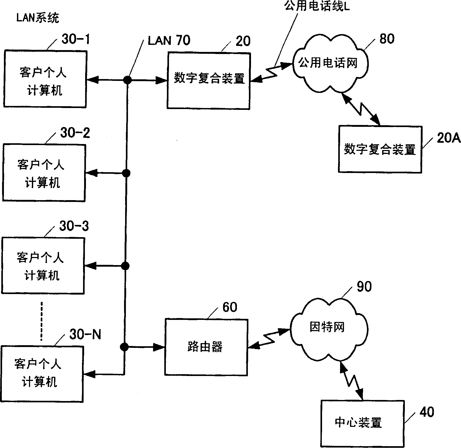
[0029] figure 1 It is a block diagram showing the configuration of a remote maintenance system according to the first embodiment of the present invention. In the remote maintenance system, a local area network system having a digital multi-function device 20 (hereinafter referred to as a facsimile device with copying, printing and scanning functions) A local area network (called LAN) and the digital composite device 20 are connected to the center device 40 through the Internet 90 .
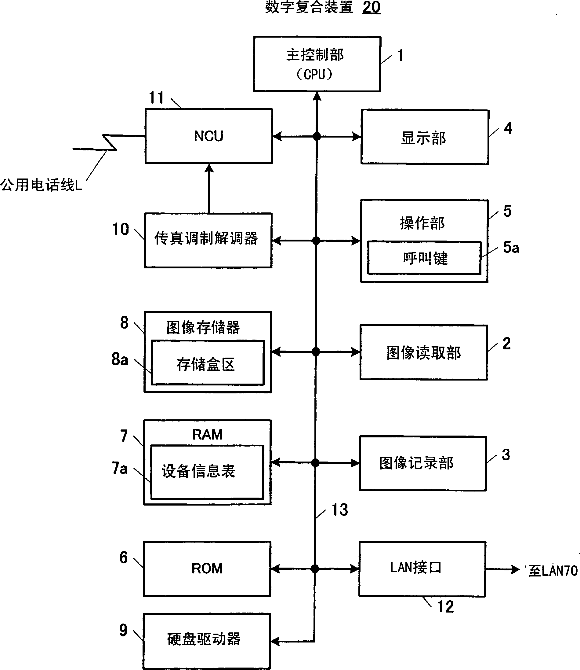
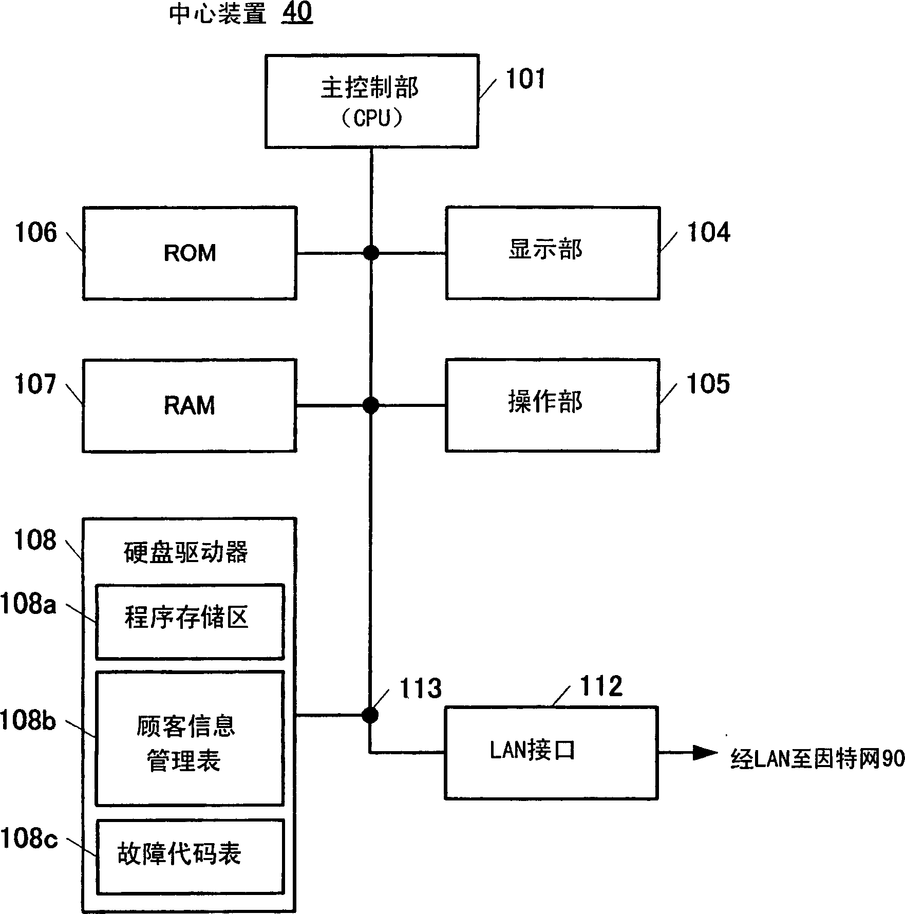
[0030] The LAN system according to the first embodiment includes N client personal computers 30-1 to 30-N (hereinafter referred to as 30 collectively), a digital composite device 20 connected to a public telephone network 80 via a public telephone line L, and The router 6...
no. 2 approach
[0058] Next, a second embodiment according to the present invention will be described with reference to the drawings. In addition, in the following second embodiment, the same symbols are attached to the same components.
[0059] Figure 8 It is a block diagram showing the configuration of a remote maintenance system according to a second embodiment of the present invention. In the remote maintenance system, a local area network system including a digital multi-function device 2020 (hereinafter referred to as a facsimile device with copying, printing and scanning functions) is provided. The local area network (LAN) and the digital multi-function device 2020 are connected to the center device 2040 through the Internet 2090 which is an IP (Internet Protocol) network.
[0060] The LAN system related to this embodiment includes N sets of client personal computers 2030-1 to 2030-N (hereinafter referred to as 2030 collectively), a digital multi-function device 2020 connected to a p...
no. 3 approach
[0083] Fig. 14 shows that instead of the center of Fig. 13 being called, by Figure 10 A flow chart of the center call process according to the third embodiment, which is another example other than the second embodiment, executed by the main control unit 2101 of the center device 2040 of .
[0084] In step S2021 of FIG. 14, it is first judged whether a center call signal has been received from the digital composite device 2020, and the process of step S2021 is repeated until it is "Yes". The customer information management table 2108b is searched for by calling the equipment information contained in the signal, and the corresponding customer management information is displayed on the display unit 2104 to report. Next, in step S2023, a call control paging signal is sent according to the retrieved corresponding customer management information, and a voice communication session is established with the corresponding digital multi-function device 2020 using, for example, SIP proced...
PUM
 Abstract
Description
Claims
Application Information
 - R&D
- Intellectual Property
- Life Sciences
- Materials
- Tech Scout
- Unparalleled Data Quality
- Higher Quality Content
- 60% Fewer Hallucinations
Browse by: Latest US Patents, China's latest patents, Technical Efficacy Thesaurus, Application Domain, Technology Topic, Popular Technical Reports.
© 2025 PatSnap. All rights reserved.Legal|Privacy policy|Modern Slavery Act Transparency Statement|Sitemap|About US| Contact US: help@patsnap.com


