LCD with function of preventing light leak, and backlight module

A liquid crystal display, backlight module technology, applied in static indicators, optics, instruments, etc., can solve the problems of inconvenient positioning of the shading tape 12, increase manufacturing costs, slow down production speed, etc., to prevent light leakage, reduce assembly steps, The effect of increasing production efficiency

Active Publication Date: 2006-12-06
AU OPTRONICS CORP
View PDF0 Cites 19 Cited by
  • Summary
  • Abstract
  • Description
  • Claims
  • Application Information

AI Technical Summary

Problems solved by technology

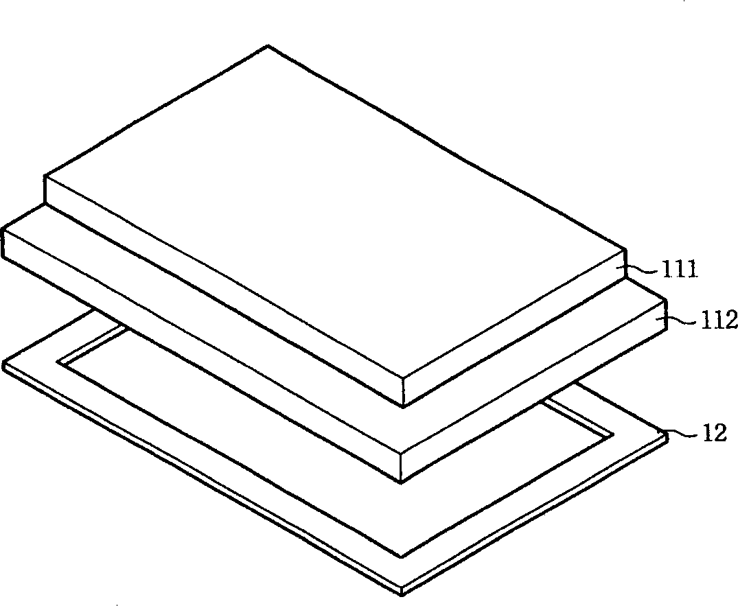
However, the positioning of the light-shielding tape 12 is inconvenient, and it is prone to be skewed.
In addition, additional man-hours are required to manually attach the shading frame
Not only is it inefficient, slows down production, but also increases manufacturing costs
In addition, in the follow

Method used


Image

  • LCD with function of preventing light leak, and backlight module
  • LCD with function of preventing light leak, and backlight module
  • LCD with function of preventing light leak, and backlight module

Examples


Example Embodiment

[0036] Figure 4 Shown is a schematic cross-sectional view of an embodiment of the liquid crystal display of the present invention. The liquid crystal display 2 includes: a liquid crystal panel 21 and a backlight module 22.

[0037] The liquid crystal panel 21 has an upper substrate 211 and a lower substrate 212. According to whether to display images, the upper and lower surfaces of the liquid crystal panel are divided into a display surface A1 and a non-display surface A2. The user views the image through the display surface A1 to obtain the required information. In addition, an opaque frame 2111 is provided on the surface of the upper substrate 211 of the liquid crystal panel 21.

[0038] The backlight module 22 further includes: a light guide plate 221, a light source 222 and a frame 223.

[0039] The light guide plate 221 is disposed on the non-display surface side of the liquid crystal panel 21, that is, on the same side as the non-display surface A2 of the liquid crystal p...


PUM


Abstract

The invention relates to a liquid crystal display with light leak proof function and the backlight module. The display includes a light guiding board, a light resource and a frame. The light resource is set at the side of the light guiding board, and the frame is set outside the light guiding board. The inner margin of the frame is set to avoid light leak that could avoid light leaking to outside from the brim of the display.

Description

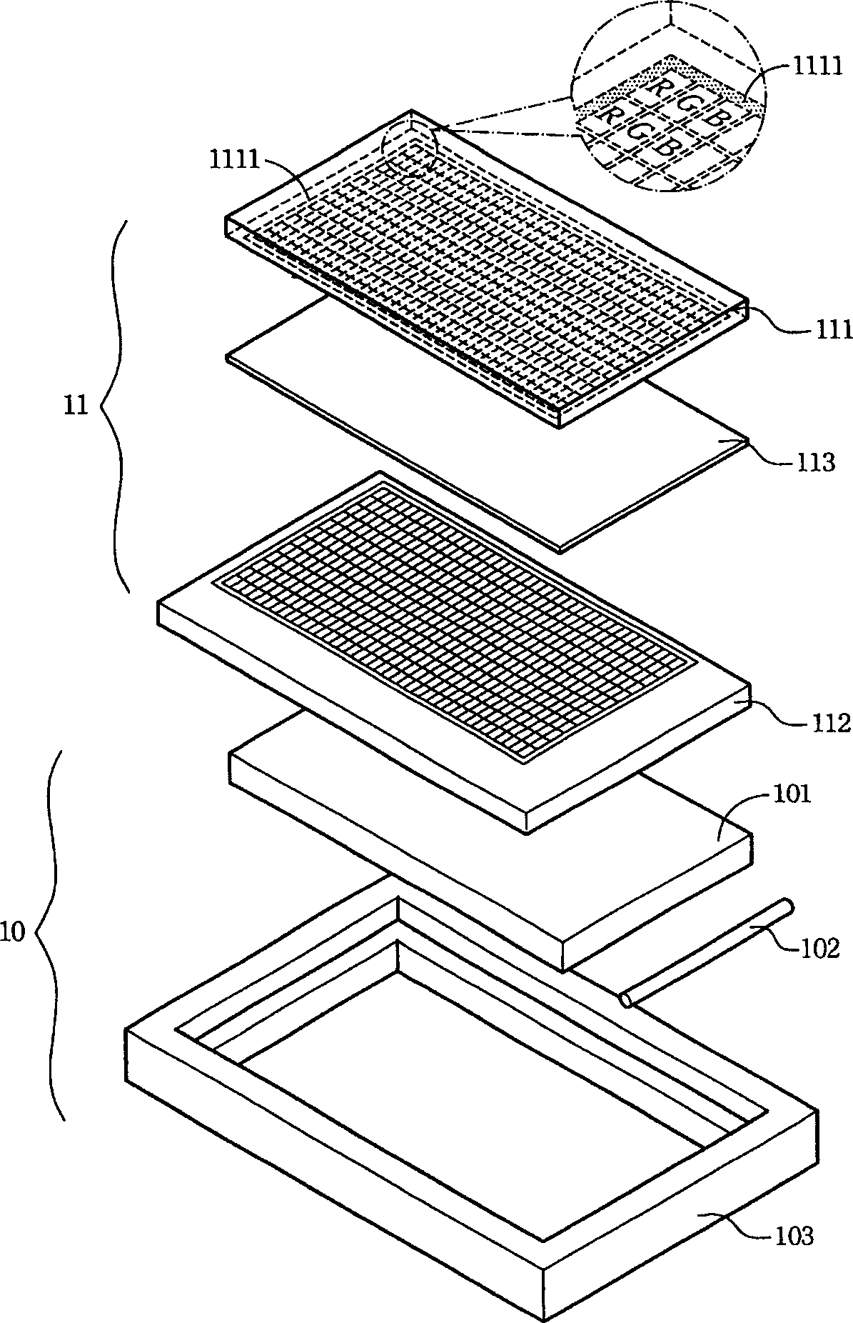
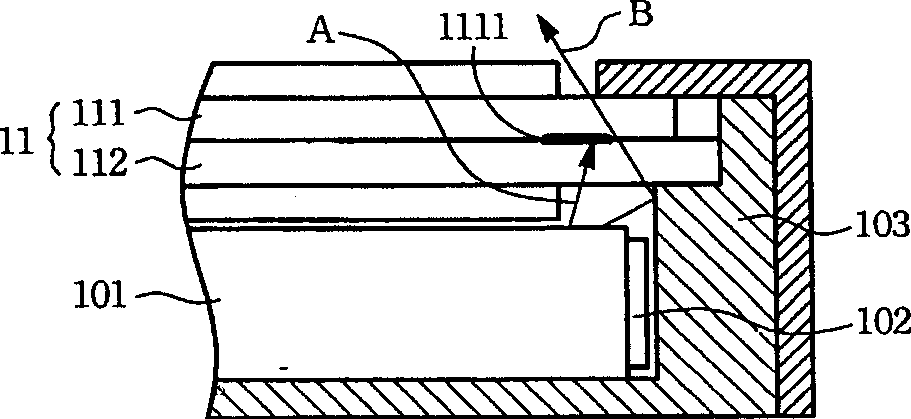
technical field [0001] The invention relates to a liquid crystal display, in particular to a liquid crystal display whose frame of a backlight module has the function of preventing light leakage. Background technique [0002] Among various image display technologies, liquid crystal displays have been widely used in various devices due to their advantages of light weight, small size, low power consumption, and no radiation. [0003] figure 1 Shown is a schematic diagram of the working principle of the liquid crystal display, which is mainly composed of a backlight module 10 and a liquid crystal panel 11, and only the main components thereof are shown here. [0004] The backlight module 10 includes a light guide plate 101 , a light tube 102 and a frame 103 . The light tube 102 is arranged at one end of the light guide plate 101 and installed in the frame 103 . After the light provided by the lamp tube 102 enters the light guide plate 101 , it is diffused and guided by the li...

Claims


Application Information

Patent Timeline
IPC IPC(8): G02F1/1335G02F1/133G09F9/35
Inventor 张豫修刘子谊
Owner AU OPTRONICS CORP
Why Eureka
Try Eureka