Communication system, and computer and device used in such system
A communication system, computer technology, applied in computing, transmission system, wireless communication and other directions, can solve problems such as user difficulty in operating users
- Summary
- Abstract
- Description
- Claims
- Application Information
AI Technical Summary
Problems solved by technology
Method used
Image

Examples
Embodiment Construction
[0051] Hereinafter, illustrative embodiments according to the present invention will be described with reference to the accompanying drawings.
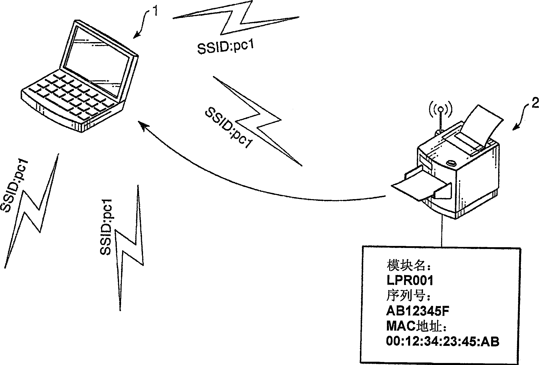
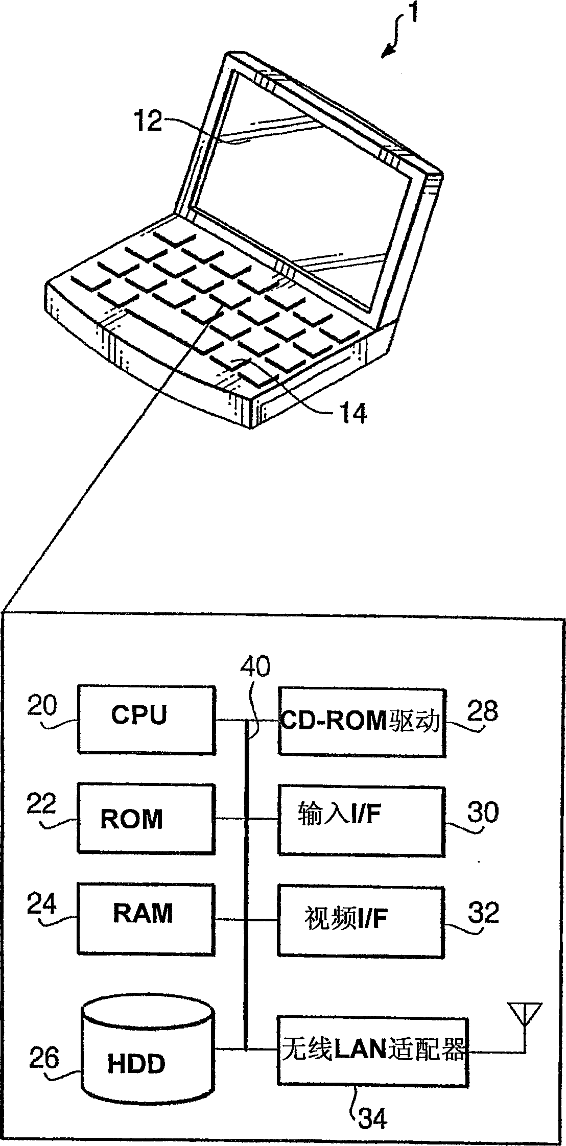
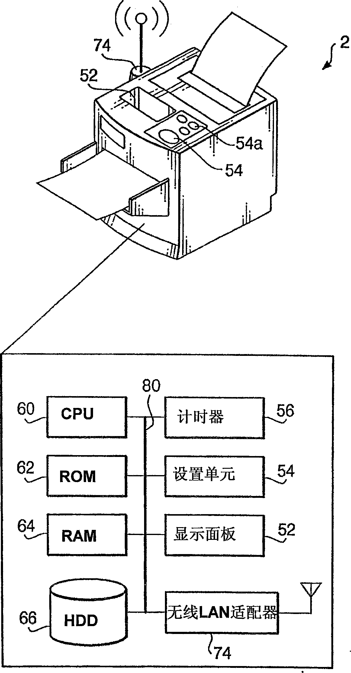
[0052] figure 1 A system configuration of a communication system 100 according to an illustrative embodiment of the present invention is illustrated. like figure 1 As shown, a PC (Personal Computer) 1 and an MFD (Multi-Function Device) 2 are equipped in a communication system 100 . The MFD 2 is configured to have various functions including a printing function and a scanning function. although figure 1 Only one multi-function device is shown in , but communication system 100 may be equipped with more than one multi-function device. The PC 1 is connected to a wireless LAN (Local Area Network) in which "pc1" is used as an SSID (Service Set Identifier).
[0053] The SSID is an identifier used to enable devices using the same SSID to communicate with each other in a wireless LAN. Since the SSID flows in the wireless network, if the ...
PUM
 Abstract
Description
Claims
Application Information