Induction heating cooker and cooking table using the same

A technology of induction heating and cooker, which is applied in the direction of induction heating, induction heating control, induction heating device, etc., and can solve the problems of increasing the heat release of the main body of the cooker and high output of the heating part, etc.

Inactive Publication Date: 2006-12-06
PANASONIC CORP
View PDF0 Cites 4 Cited by
  • Summary
  • Abstract
  • Description
  • Claims
  • Application Information

AI Technical Summary

Problems solved by technology

[0004] However, it is not considered to increase the heat output of the main body of the coo

Method used


Image

  • Induction heating cooker and cooking table using the same
  • Induction heating cooker and cooking table using the same
  • Induction heating cooker and cooking table using the same

Examples


Embodiment Construction

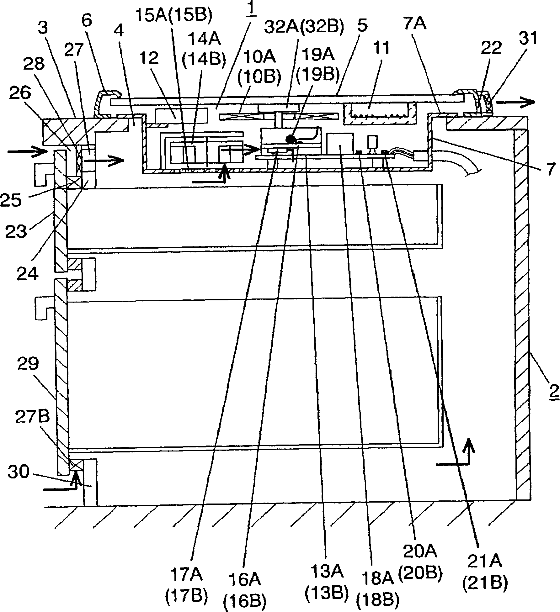
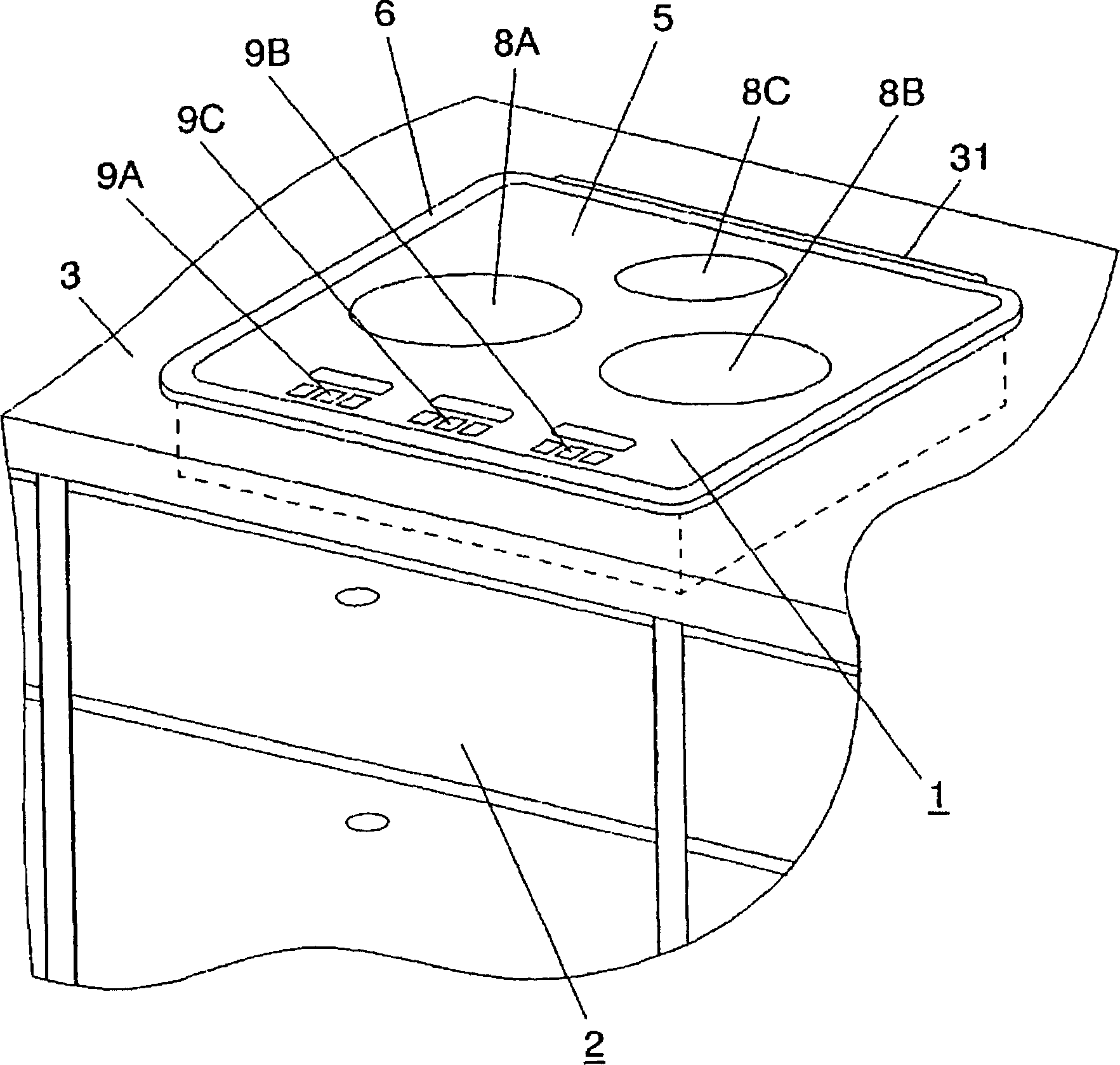
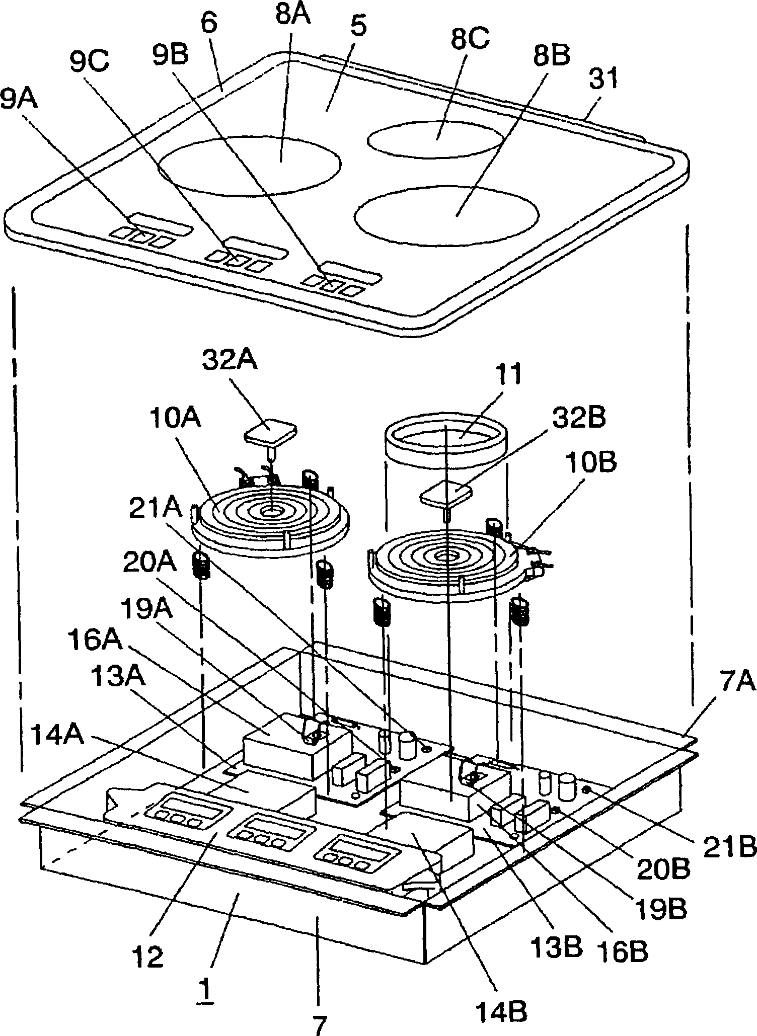
[0013] figure 1 , figure 2 A cross-sectional view and a perspective view of a cooking table including an induction heating cooker according to an embodiment of the present invention are respectively shown, image 3 An exploded perspective view showing the induction heating cooker.

[0014] The cooker 1 is fitted into the opening 4 of the counter top 3 provided on the upper surface of the kitchen cabinet 2 from above, and is installed. The cooker 1 has a top plate 5 and a plate frame (hereinafter referred to as a frame) 6 covering the periphery thereof on the upper surface. The top plate 5 is made of crystallized glass as a raw material. In the cooker 1 , the upper end of the outer profile 7 , which is a portion that enters the opening 4 , is engaged with the table top 3 bent into a flange shape. Top plate 5 , frame 6 , outer contour 7 form the housing of cooker 1 . Heating sections 8A, 8B, and 8C are printed on top plate 5 , and operating sections 9A, 9B, and 9C corresp...


PUM


Abstract

An induction heating cooker includes: an external shell, a heating coil, a power source circuit, a plurality of temperature detection elements, and a control unit for controlling output of the heating coil. The heating coil is arranged in the external shell. The power source circuit has a plurality of heating elements and supplies a high-frequency current to the heating coil. The temperature detection elements respectively detect temperatures of the heating elements. When one of the temperatures detected by the temperature detection elements has reached a temperature predetermined for each of the temperature detection elements, the control unit lowers the output of the heating coil. When one of the temperatures detected by the temperature detection elements is higher than a first temperature and has reached a second temperature predetermined for each of the temperature detection elements, the output of the heating coil is further lowered.

Description

technical field [0001] The invention relates to an induction heating cooker embedded in cabinets such as kitchens. Background technique [0002] Conventionally, an induction heating cooker is used that is embedded in a counter, has an air inlet provided on an outer contour facing the inside of the counter, and an exhaust port is provided on the upper outer side of the counter. Such an induction heating cooker is disclosed in, for example, JP-A-11-354263. [0003] Figure 5 , Figure 6 A perspective view and a cross-sectional view of the above-mentioned conventional induction heating cooker are respectively shown. The cooker main body 41 is embedded in the upper opening 43 of the kitchen cabinet 42 , and the cooker 41 is provided with a heating coil 44 , a circuit board 45 and a cooling fan 46 . A suction port 47 is provided under the cooker 41 , and an exhaust port 48 is provided on the rear side wall of the cooker 41 . In this structure, by inserting and fixing the cook...

Claims


Application Information

Patent Timeline
IPC IPC(8): H05B6/12H05B6/06
CPCH05B2213/07H05B6/1263H05B6/062
Inventor 冈田和一细井弘一
Owner PANASONIC CORP
Why Eureka
Try Eureka