Oxygen sensor

A technology of oxygen sensor and casing, which is applied in the improvement field of oxygen sensor, and can solve the problem of easy damage of sealing rubber

Inactive Publication Date: 2006-12-13
HITACHI LTD
View PDF2 Cites 4 Cited by
  • Summary
  • Abstract
  • Description
  • Claims
  • Application Information

AI Technical Summary

Problems solved by technology

[0003] When this type of oxygen sensor is used to detect the oxygen concentration in the exhaust pipe of the internal combustion engine, since the sealing rubber is close to the exhaust pipe with high temperature, the sealing rubber is easily damaged by heat

Method used


Image

  • Oxygen sensor
  • Oxygen sensor
  • Oxygen sensor

Examples


Embodiment Construction

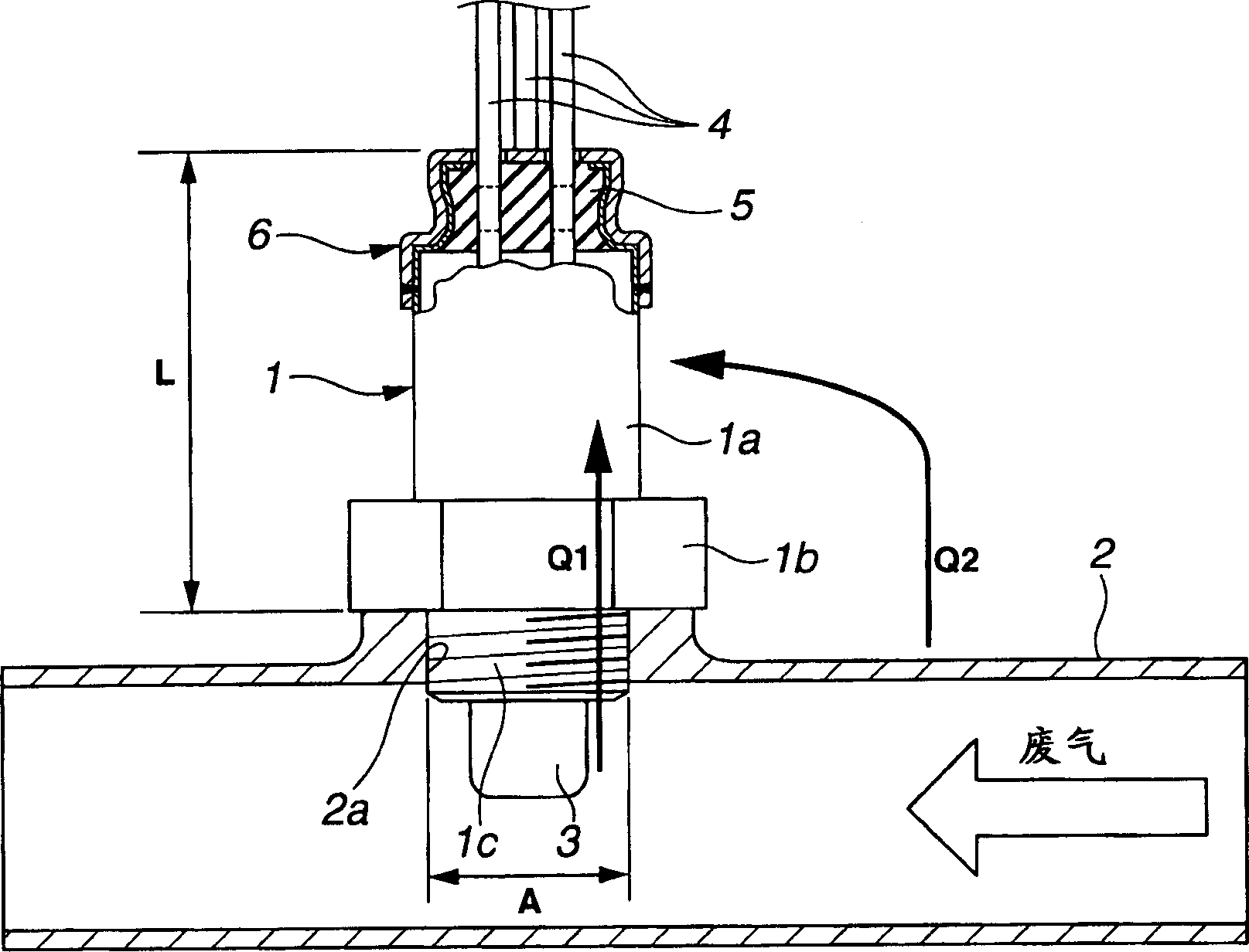
[0015] Referring to the accompanying drawings, an embodiment of the oxygen sensor of the present invention is illustrated in conjunction with an exhaust pipe installed on an automobile internal combustion engine, wherein the oxygen sensor is installed on the exhaust pipe for detecting the air-fuel ratio of the exhaust gas.

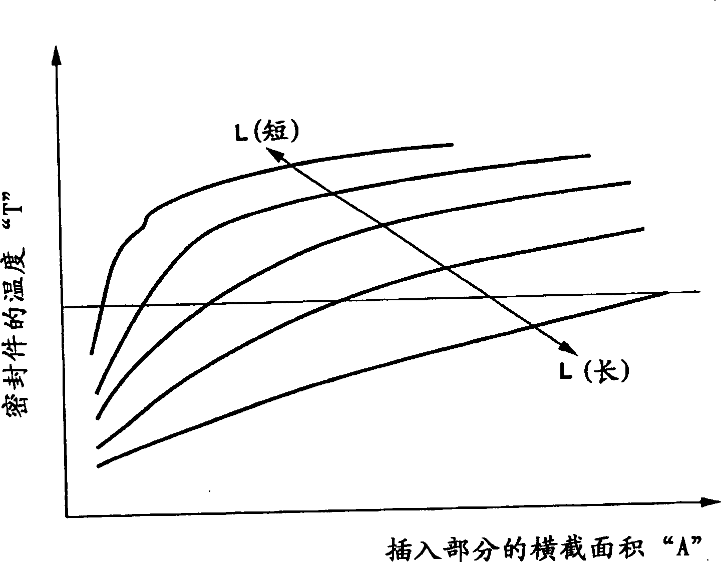
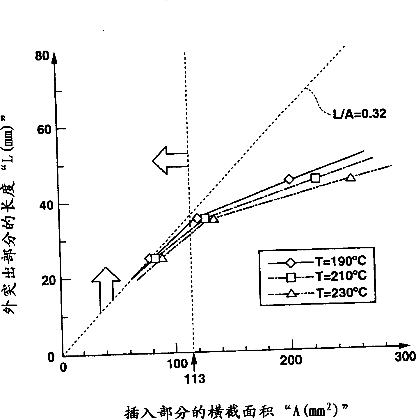
[0016] figure 1 is a side view of an embodiment of the oxygen sensor of the present invention, partially cut away, and the oxygen sensor is installed on the exhaust pipe; figure 2 yes means figure 1 A curve of the relationship between the cross-sectional area of ​​the inserted part of the oxygen sensor and the temperature of the seal; and image 3 yes means figure 1 The curve of the relationship between the cross-sectional area of ​​the insertion part of the oxygen sensor and the length of the outer protrusion.

[0017] Such as figure 1 As shown, the exhaust pipe 2 has an internally threaded hole 2a as a through hole on its side wall, and the external...


PUM


Abstract

An oxygen sensor includes a generally cylindrical casing. A detecting section is disposed at an axially one end side of the casing so as to detect a concentration of oxygen. Lead wires are electrically connected with the detecting section and outwardly extend through an axially other end side of the casing. A seal member is disposed inside an end section located at the axially other end side of the casing. The lead wires pierce the seal member. An insertion section is located at the axially one end side of the casing so that the detecting section projects over the insertion section. The insertion section is inserted into a through-hole formed in a wall of an exhaust pipe, so as to install the oxygen sensor to the exhaust pipe in a condition where the detecting section projects into the exhaust pipe. A ratio of a length of an outer projecting section of the oxygen sensor to a cross-sectional area of the insertion section inserted into the through-hole is set at a value not lower than a value at which a temperature in the seal member reaches a heat resistant temperature limit of the seal member.

Description

field of invention [0001] The present invention relates to improvements in oxygen sensors. Background technique [0002] So far, various types of oxygen sensors have been developed and put into practical use. One such oxygen sensor is disclosed in Japanese Patent Provisional Publication No. 9-178694. The oxygen sensor includes a substantially cylindrical housing having a detection portion at one axial end thereof and a sealing rubber ensuring hermetic sealing inside the housing at the other axial end. Sealing rubber is used to plug the opening at the other end of the housing. Lead wires (insulated wires) pierce the sealing rubber and are electrically connected to the detection portion. [0003] When this type of oxygen sensor is used to detect the oxygen concentration of the exhaust pipe of the internal combustion engine, since the sealing rubber is close to the exhaust pipe with high temperature, the sealing rubber is easily damaged by heat. Therefore, in the convention...

Claims


Application Information

Patent Timeline
Patent Type & Authority Applications(China)
IPC IPC(8): G01N27/409G01N27/12
CPCG01N27/4078G01N27/407
Inventor 一柳太内川晶塚田正夫
Owner HITACHI LTD
Why Eureka
Try Eureka