

Installation work management method, installation machine and preparation support method, installation assembly line
A technology of operation management and installation machine, which is applied in the direction of assembling printed circuits, electrical components, electrical components, etc. with electrical components, and can solve problems such as inability to obtain production efficiency, component shortages and errors
- Summary
- Abstract
- Description
- Claims
- Application Information
AI Technical Summary
Problems solved by technology
Method used
Image

Examples
no. 1 Embodiment approach
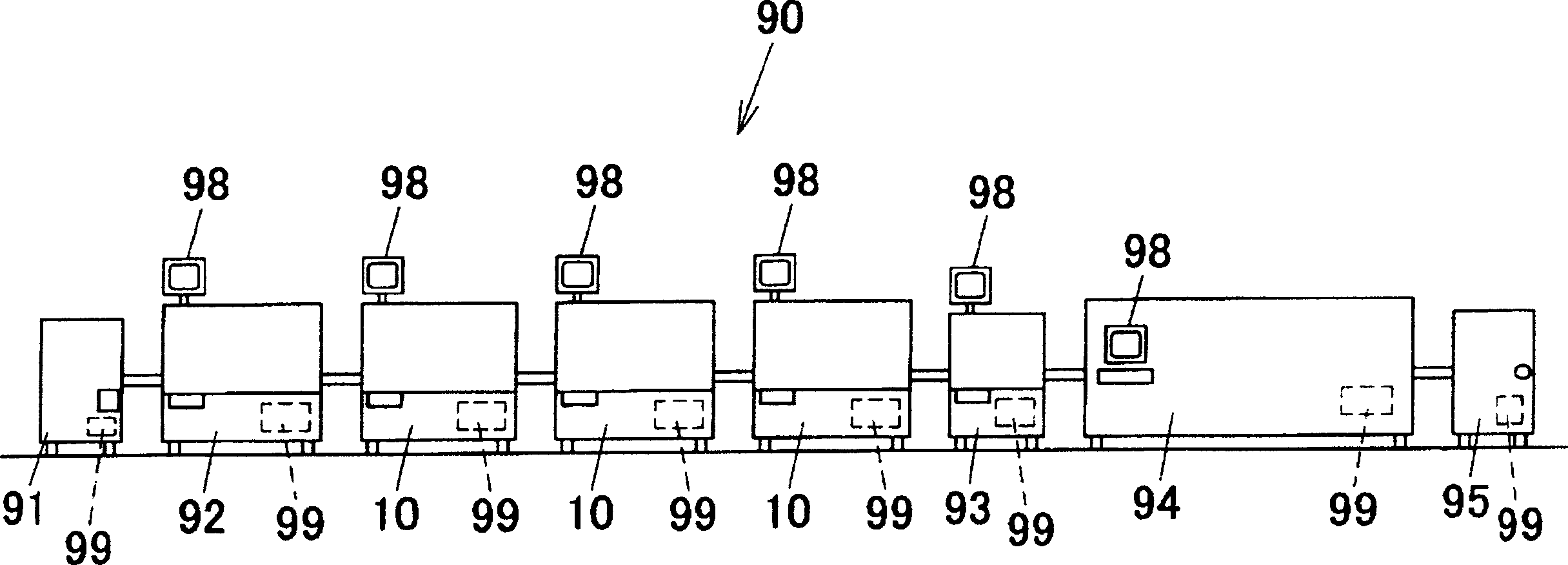
[0099] figure 1 It is a simplified side view of the assembly line suitable for the present invention. Such as figure 1 As shown, in the assembly line 90, a substrate loading machine 91, a printing machine 92, multiple (three) mounting machines 10..., an inspection machine 93, a reflow furnace 94, and a substrate are arranged in parallel from the upstream side to the downstream side of the production line. Move out machine 95 and other equipment.
[0100] The substrate loading machine 91 is a device that accommodates a plurality of substrates and sequentially loads the substrates into the printer 92 . The printer 92 is a device for applying solder paste by printing to the substrate processing area to be carried in. The mounting machine 10 ... is a device for mounting electronic components on a predetermined position on a board. The inspection machine 93 is a device for inspecting the mounting state of the electronic components mounted on the board. The reflow furnace 94 is...
no. 2 Embodiment approach
[0197] Next, a second embodiment of the present invention will be described. The mounting line applied to the second embodiment, the basic structure of the mounting machine included in the mounting line, and the functions of the component supply part of the mounting machine are similar to those of the first embodiment ( figure 1 ˜ FIG. 3 ) are the same, and therefore description thereof will be omitted. Only the differences are detailed below.
[0198] In the mounting line 90 of the second embodiment, the mounting work of various components on substrates to be produced is distributed to the component supply devices mounted on arbitrary mounting machines of the mounting line 90 . Then, for components not mounted on any mounting machine of the mounting line 90 among the required components, the operator is notified and urged to mount on any mounting machine of the mounting line 90 .
[0199] According to this operation method, if the component supply device that supplies the r...
no. 3 Embodiment approach
[0256] Next, a third embodiment of the present invention will be described. The mounting line applied to the third embodiment, the basic structure of the mounting machine included in the mounting line, and the functions of the component supply part of the mounting machine are the same as those of the first embodiment ( figure 1 ~ Fig. 3) are the same, so the description thereof will be omitted. Hereinafter, only the different points will be described in detail.
[0257] The mounting line 90 of the third embodiment is basically the same as that of the first embodiment. According to the disclosed optimization method, which mounting machine 10 is allocated to each mounting operation is obtained, and as the sequence of the initial production program, each The order of the mounting work assigned to each mounting machine, based on this, corresponding to the configuration of the component supply device currently installed on any mounting machine of the mounting line 90, the mounting...
PUM
 Abstract
Description
Claims
Application Information