Guiding magnet system and magnetic levitation vehicle equipped therewith

A magnetic levitation, magnet technology, applied in railway vehicles, vehicle components, transportation and packaging, etc., to achieve the effect of weight reduction

Active Publication Date: 2006-12-13
THYSSENKRUPP TRANSRAPID
View PDF2 Cites 6 Cited by
  • Summary
  • Abstract
  • Description
  • Claims
  • Application Information

AI Technical Summary

Problems solved by technology

Moreover, the length of the windings and the weight of the guide magnet system, which is substantially integrally determined by its iron composition, cannot be optimal

Method used


Image

  • Guiding magnet system and magnetic levitation vehicle equipped therewith
  • Guiding magnet system and magnetic levitation vehicle equipped therewith
  • Guiding magnet system and magnetic levitation vehicle equipped therewith

Examples


Embodiment Construction

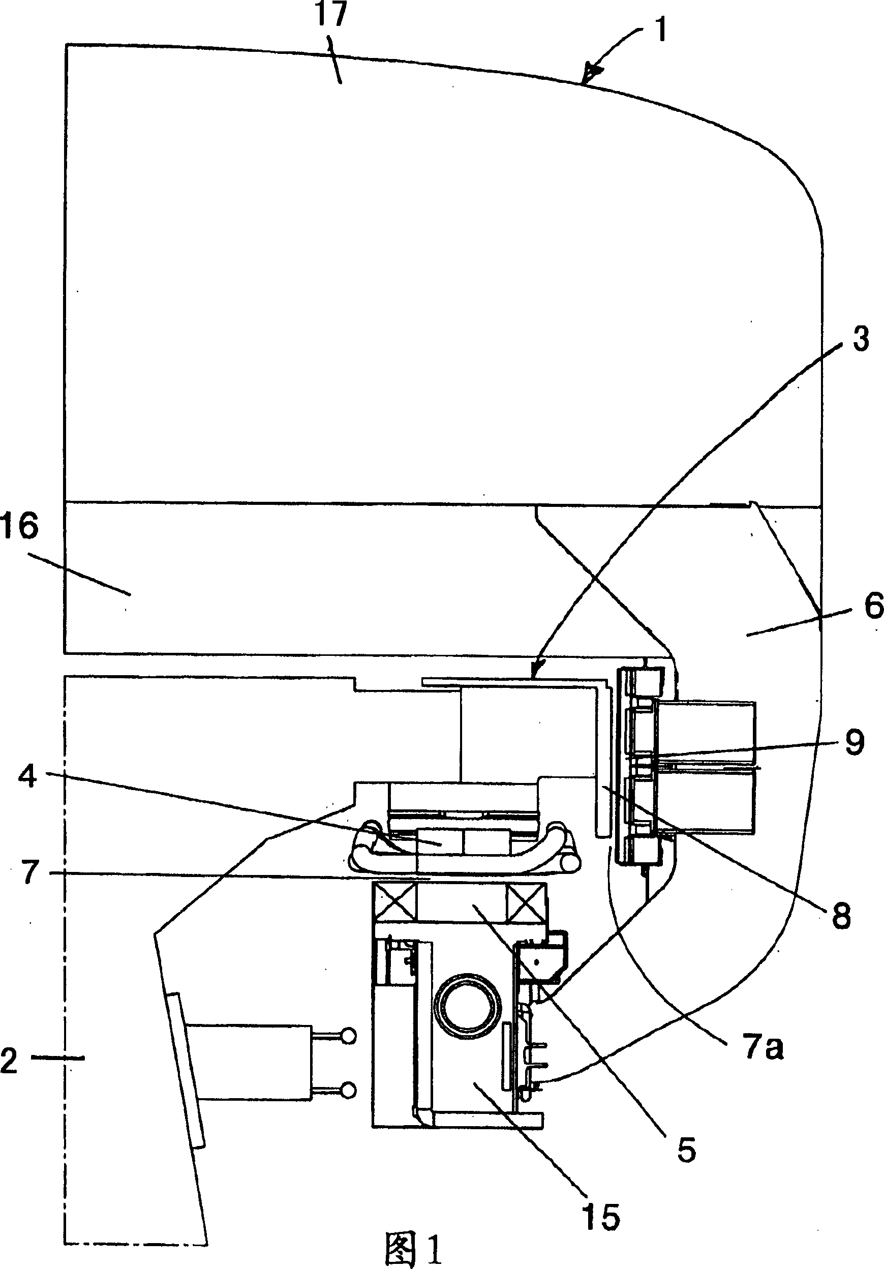
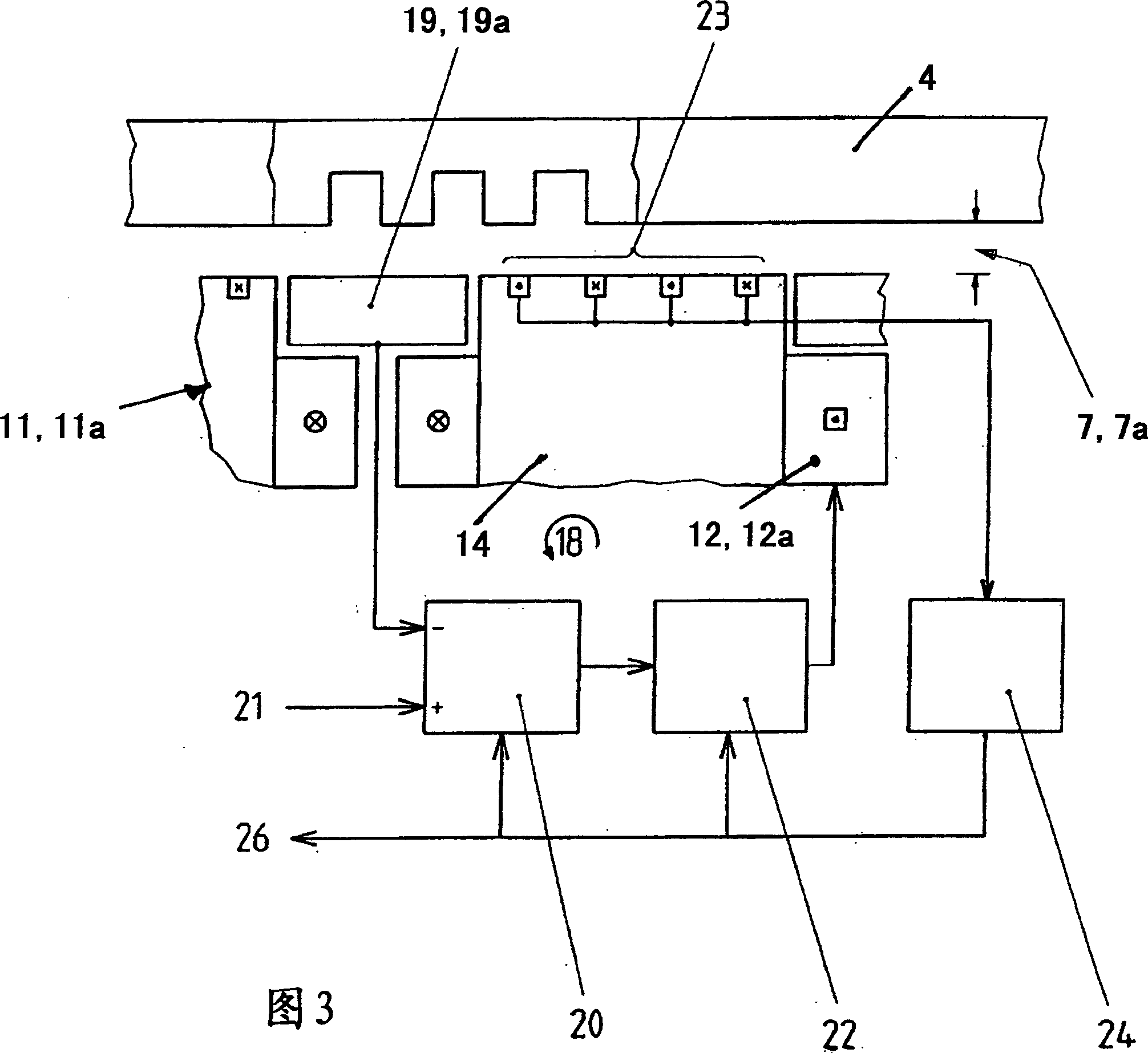
[0019] Figure 1 schematically represents a cross-section through a magnetically levitated vehicle 1 conventionally movably mounted on guide rails extending in the longitudinal direction of the route, said guide rails comprising beams made of steel and / or concrete (support) 2 and the guide rail plate 3 installed on it. The thrust of the magnetically levitated vehicle 1 is achieved by a long stator motor comprising stator laminations 4 attached below the rail plate 3 and arranged one behind the other in its longitudinal direction. The stator laminations 4 comprise an alternating succession of teeth and slots, shown only in FIG. 3 , into which windings supplied with three-phase currents of variable amplitude and frequency are inserted. The actual excitation field of the long stator motor is generated by at least one first magnet arrangement which plays the role of carrying (supporting) the magnet 5 attached to the magnetic levitation vehicle 1 by at least one lateral support brac...


PUM


Abstract

The present invention relates to one kind of guiding magnet system for magnetic suspension vehicle. The guiding magnet system includes several magnet devices with iron core, and the iron core with two planes for windings extends in the longitudinal direction of the vehicle. Windings in even number are arranged in each of the planes for windings. In one end of the magnet device, there are paired electrically serial windings connected to specified control loops; and in the other end, there are either two pairs of similar windings or only one pair of windings. The present invention also relates to one kind of magnetic suspension vehicle with the said guiding magnet system.

Description

technical field [0001] The invention relates to a guiding magnet system of the kind mentioned in the preamble of claim 1 and to a magnetically levitated vehicle equipped with it. Background technique [0002] This type of guide magnet system is used for the purpose of keeping maglev vehicles within the track gauge, especially during curves, and is used to control the magnet arrangement in such a way by means of control circuits and gap sensors assigned to them , so that the gap between their magnetic poles and the transverse guide rail (hereinafter referred to as the guide gap) is always kept at a preselected value, for example 10mm. With prior art guide magnet systems, each vehicle or vehicle segment is provided with two sets of three guide magnets each arranged in series and one braking magnet each arranged between these two sets in the longitudinal direction of the vehicle, so that used for this purpose. Each guide magnet is formed by a magnet arrangement with a core ex...

Claims


Application Information

Patent Timeline
Patent Type & Authority Applications(China)
IPC IPC(8): B60L13/08
CPCB60L2200/26
Inventor W·哈恩F·勒泽
Owner THYSSENKRUPP TRANSRAPID
Why Eureka
Try Eureka