

Head-rest type vehicle-mounted telephone and auto using the telephone
A car phone and headrest technology, applied in vehicle parts, transportation and packaging, etc., can solve the problems of manual operation and inability to operate the car phone conveniently.
- Summary
- Abstract
- Description
- Claims
- Application Information
AI Technical Summary
Problems solved by technology
Method used
Image

Examples
Embodiment Construction
[0018] The present invention will be further described below in conjunction with the accompanying drawings and embodiments.
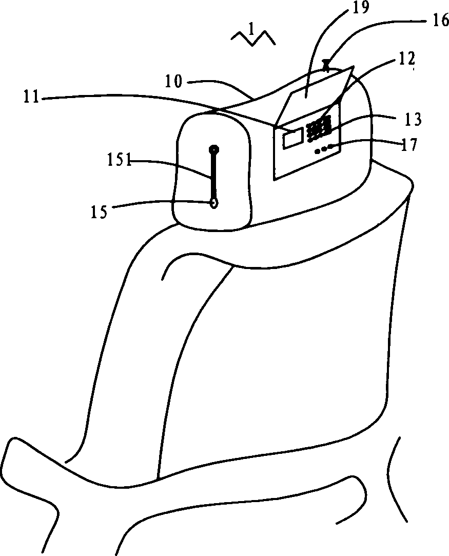
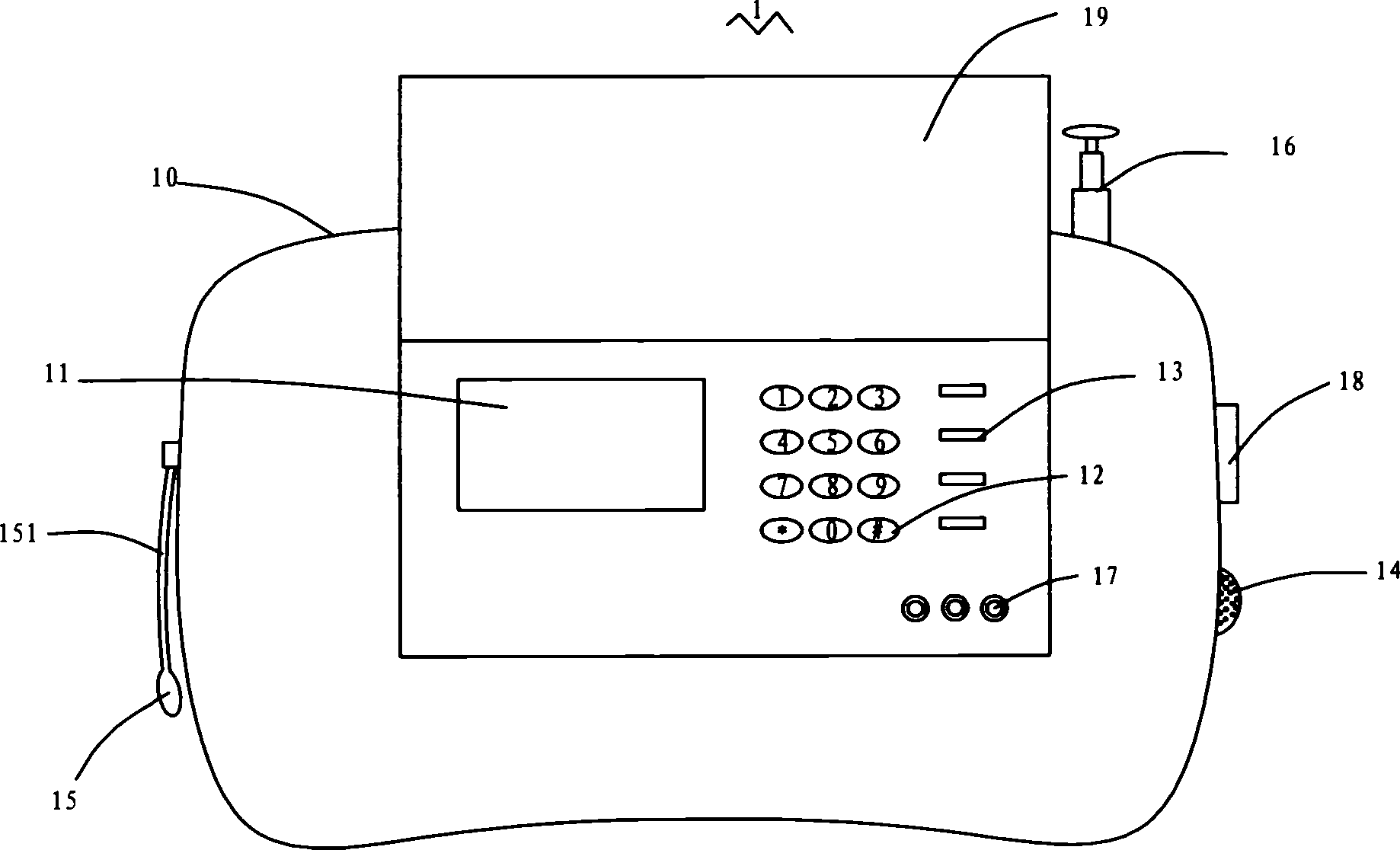
[0019] see figure 1 and figure 2 ,in, figure 1 It is a structural schematic diagram of an embodiment of the car phone of the present invention, figure 2 Yes figure 1 Front view of the car phone shown. The car phone 1 of this embodiment includes a headrest-shaped base 10, a phone body (not shown) and peripheral devices. Wherein, the main body of the phone is arranged in the frame of the headrest 10, and the main body of the phone may include: a main control module, a power control module, a mobile communication module and a voice input / output module. Simultaneously, peripheral devices such as a display screen 11 , number keys 12 , function keys 13 and external jacks 17 are arranged on the frame body of the headrest 10 facing the rear row of seats. Peripheral devices such as a hands-free speaker 14 , a microphone 15 , a retractable antenna 16 , an...
PUM
 Abstract
Description
Claims
Application Information