Laser scanning device

A technology of laser scanning device and light source projection, applied in the direction of optics, optical components, instruments, etc., can solve problems such as complex structures, and achieve the effect of preventing pollution

Inactive Publication Date: 2006-12-20
HEWLETT PACKARD DEV CO LP
View PDF0 Cites 2 Cited by
  • Summary
  • Abstract
  • Description
  • Claims
  • Application Information

AI Technical Summary

Problems solved by technology

However, the conventional light blocking unit has multiple parts, such as an elastic member, a shutter, and a driving motor, and the conventional light blocking unit requires a complicated structure and a dedicated driving source

Method used


Image

  • Laser scanning device
  • Laser scanning device
  • Laser scanning device

Examples


Embodiment Construction

[0038] Hereinafter, some exemplary embodiments of the present invention will be described in detail with reference to the accompanying drawings.

[0039] The matters defined in the detailed description, such as a detailed structure and its elements, are provided to help a comprehensive understanding of the invention. Therefore, it is apparent that the present invention can be carried out without those defined matters. Also, well-known functions and constructions are omitted to provide a clear and concise detailed description.

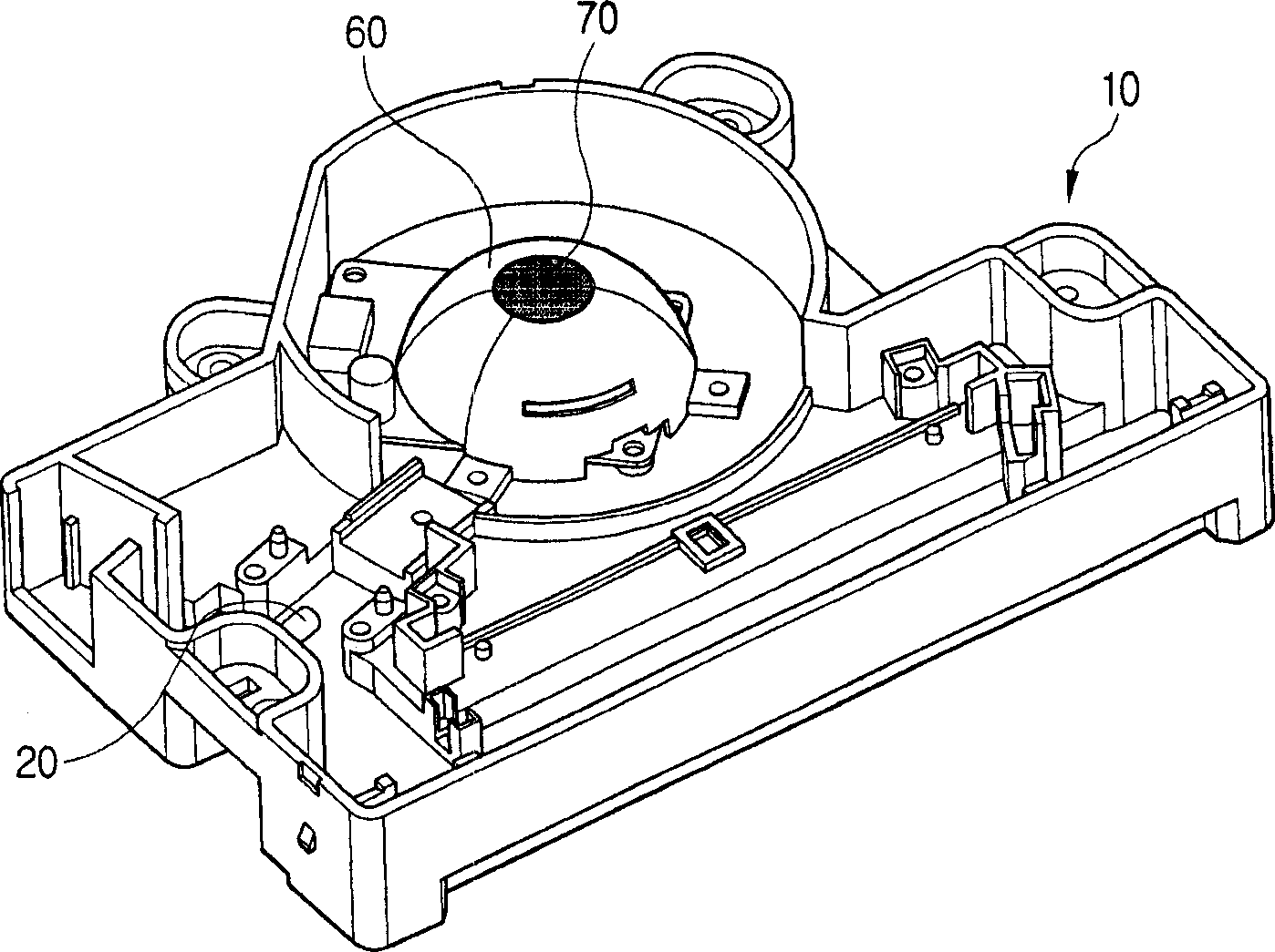
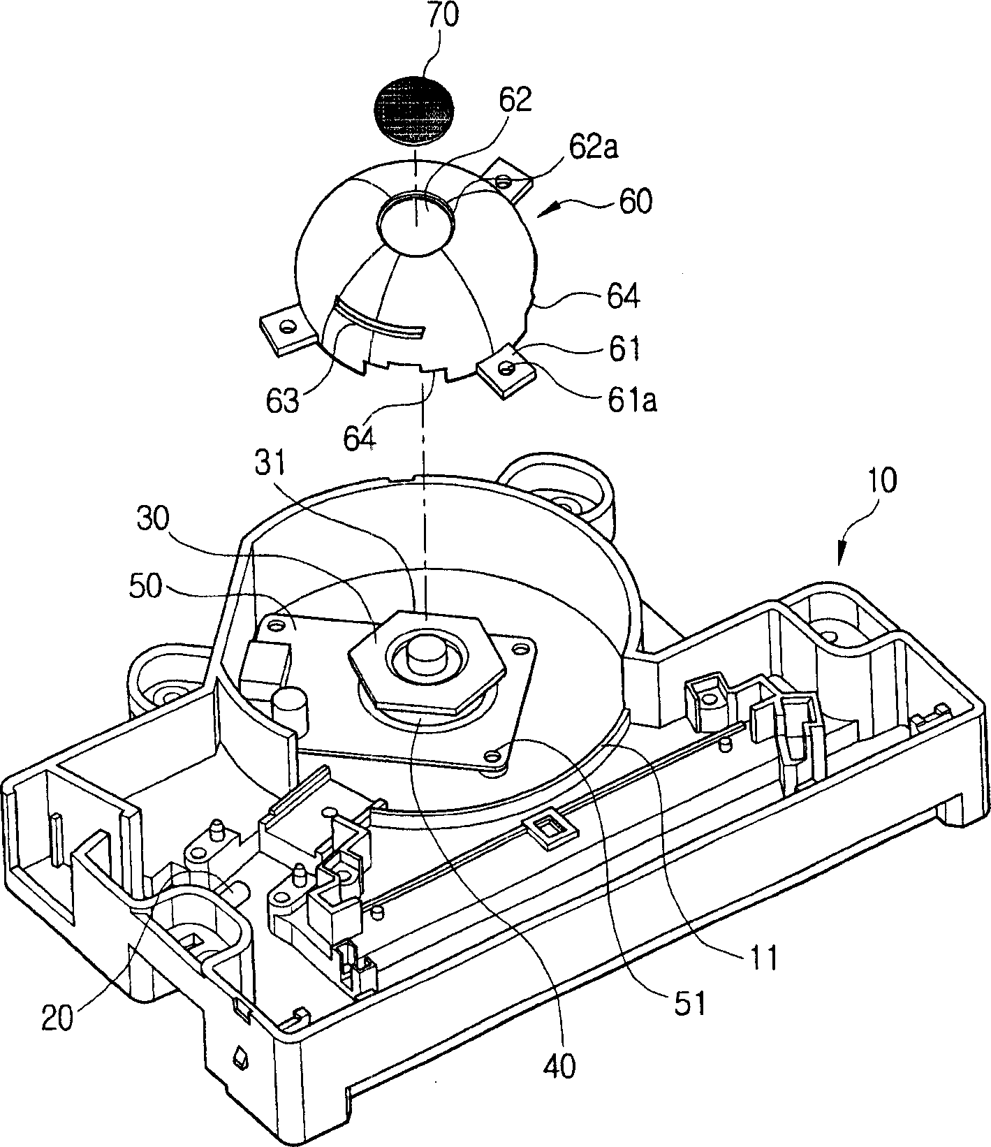
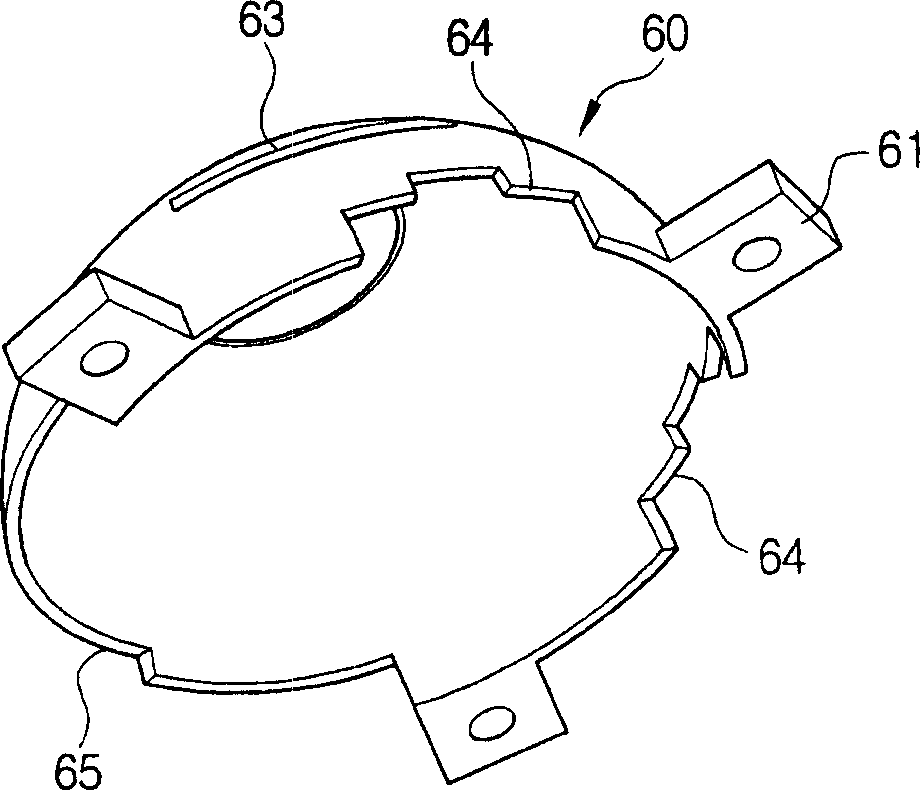
[0040] refer to figure 1 and 2 , The laser scanning device according to an exemplary embodiment of the present invention includes: a device body 10 ; a light source 20 installed in the device body 10 ; and a rotating polygon mirror 30 deflecting light projected from the light source 20 . The drive motor 40 rotates the rotary polygon mirror 30 . The circuit board 50 controls the drive motor 40 . The cover member 60 covers the rotating polygon mirror...


PUM


Abstract

A laser scanning device includes a device body, and a rotating polygonal mirror rotatably mounted in the device body and deflecting light projected from a light source. A cover member is mounted in the device body to cover the rotating polygonal mirror. The cover member has a slit for transmitting the light and an influent hole for letting external air flow in, and forms an air current rotating and descending at high speed around the rotating polygonal mirror. A dust collection member filters off dust included in the air flowing into the cover member through the influent hole by the air current generated in the cover member.

Description

technical field [0001] The present invention relates to a laser scanning device for deflecting incident light in a predetermined direction. Background technique [0002] Generally, image forming apparatuses such as laser printers, copiers, scanners, and multifunction devices have laser scanning devices. [0003] In a laser scanning device, light projected from a light source is deflected in a predetermined direction by a directional reflection surface of a rotating polygon mirror rotating at high speed. The deflected light passes through a predetermined optical system and enters a photosensitive medium such as a photosensitive drum. [0004] As imaging devices tend toward high-speed performance, the rotation speed of the rotating polygon mirror increases. When the rotating polygon mirror is rotated at high speed, the ambient air of the rotating polygon mirror including internal dust generates a rapid airflow in the main body of the laser scanning device. Therefore, dust d...

Claims


Application Information

Patent Timeline
IPC IPC(8): G02B26/10
CPCG03G15/04G03G21/16G03G21/1832G03G2215/0402G03G2221/1636
Inventor 卓庆模
Owner HEWLETT PACKARD DEV CO LP
Why Eureka
Try Eureka