
Bias bridge type short circuit current limiter

A technology of short-circuit current and limiter, which is applied in the protection of reacting to overcurrent, emergency protection circuit devices for limiting overcurrent/overvoltage, electrical components, etc. 500kV level power grid application, large harmonics and other problems, to achieve the effect of quickly limiting short-circuit current

Inactive Publication Date: 2006-12-27
SHANGHAI JIAO TONG UNIV
View PDF0 Cites 10 Cited by
  • Summary
  • Abstract
  • Description
  • Claims
  • Application Information

AI Technical Summary

Problems solved by technology

There are two problems with this current limiter. One is that the thyristor has to pass the short-circuit current in the case of a short circuit, which fundamentally limits the application of high power, and it is difficult to rise to the application of the 500kV power grid.
Second, the use of a fully-controlled bridge-type superconducting fault current limiter will introduce a large number of harmonics, and a fault detection device is required

Method used


Image

  • Bias bridge type short circuit current limiter
  • Bias bridge type short circuit current limiter

Examples


Embodiment Construction

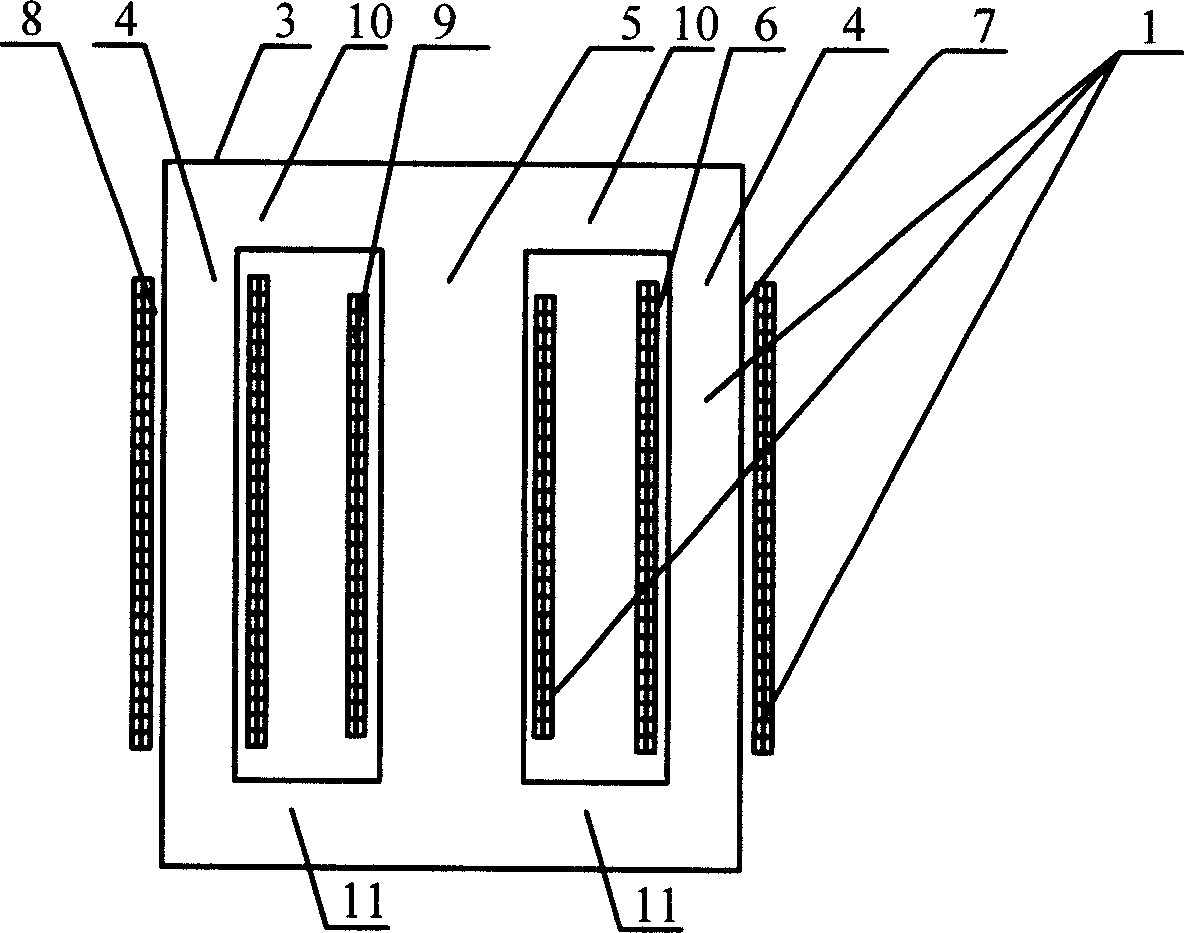
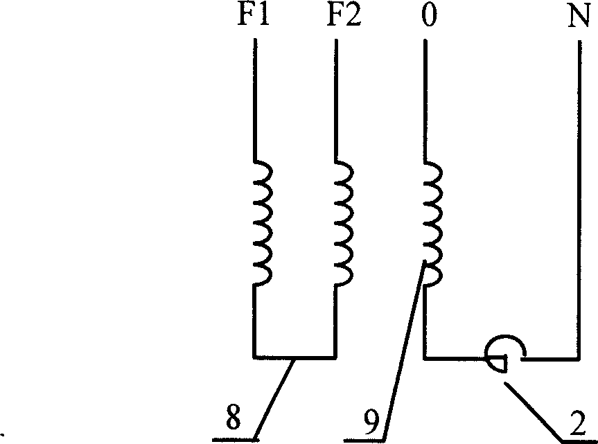
[0012] Such as figure 1 , 2 As shown, the present invention includes: a saturated reactance bridge circuit 1 and a current-limiting reactor 2 . The saturated reactance bridge 1 is composed of an AC winding 8, a bias winding 9 and a three-column iron core 3. The AC winding 8 is two series-connected cylindrical packages, which are respectively set on the two side columns 4 of the three-column iron core. The magnetic winding 9 is a rectangular cylindrical package, which is sleeved on the central column 5 of the three-column iron core 3 . The current-limiting reactor 2 forms a bias current loop through the bias power supply and the bias winding 9 sleeved on the middle column 5 of the three-column iron core 3 .

[0013] Between the AC winding 8, the bias winding 9 and the three-column iron core 3 are insulating layers 6 and cooling holes 7, and the connection between the middle column 5 and the two side columns 4 is an upper yoke 10 and a lower yoke 11, Between the AC winding 8,...


PUM


Abstract

The short-circuit current limiter as bias bridge comprises: a saturation reactance circuit with an ac winding as two cylinder packets in series, a rectangular-cylinder bias winding, and T-shaped iron core to accommodate former packets; and a limiting reactor to form a bias current loop with former winding. This invention takes up less than 1% rated voltage, generates no additional harmonic, and can limit short-circuit current within 4-times conventional value.

Description

technical field [0001] The invention relates to a device in the field of electrical technology, in particular to a bias bridge type short-circuit current limiter. Background technique [0002] With the continuous development and expansion of the power system, the short-circuit capacity of the system has increased rapidly, reaching the level where the interrupting capacity of conventional circuit breakers cannot meet the requirements. The use of effective current limiting technology in the system, on the one hand, can limit the short-circuit current to a lower level to meet the requirements of the breaking capacity, on the other hand, it can greatly reduce the design value of the dynamic and thermal stability of the electrical equipment, and has the advantages of Great economic value and social significance. At present, superconducting short-circuit current limiters are more researched. The application technology of superconducting technology in high-voltage and high-power a...

Claims


Application Information

Patent Timeline
Patent Type & Authority Applications(China)
IPC IPC(8): H02H9/02H02H3/08
Inventor 蔡旭腾乐天金之俭姜益民凌志斌潘艳霞
Owner SHANGHAI JIAO TONG UNIV
Learn More