Flat plate heat transfer device

A technology of flat panels and heat sources, applied in clothing, cooling/ventilation/heating transformation, hats, etc., can solve the problems of reduced flow rate, easy crushing of metal shells, weak ability to resist external impacts, etc.

Inactive Publication Date: 2006-12-27
LG CABLE LTD (KR)
View PDF1 Cites 11 Cited by
  • Summary
  • Abstract
  • Description
  • Claims
  • Application Information

AI Technical Summary

Problems solved by technology

If there is a significant difference between the time it takes for the condensed working fluid to return and the time it takes for the evaporated working fluid to diffuse, the flow rate of the working fluid that can be circulated per unit time decreases, and thus the heat transfer performance of the flat plate heat transfer dev...

Method used


Image

  • Flat plate heat transfer device
  • Flat plate heat transfer device
  • Flat plate heat transfer device

Examples


Embodiment Construction

[0040] Hereinafter, in order to explain the present invention in detail, the embodiments will be described, and the detailed description will be provided with reference to the accompanying drawings for better understanding of the present invention. However, the embodiments of the present invention can be modified in various ways, and it should not be construed that the scope of the present invention is limited to the embodiments described below. The embodiments of the present invention are provided only to provide clearer and more precise descriptions for those skilled in the art. In the drawings, the same reference numerals denote the same elements.

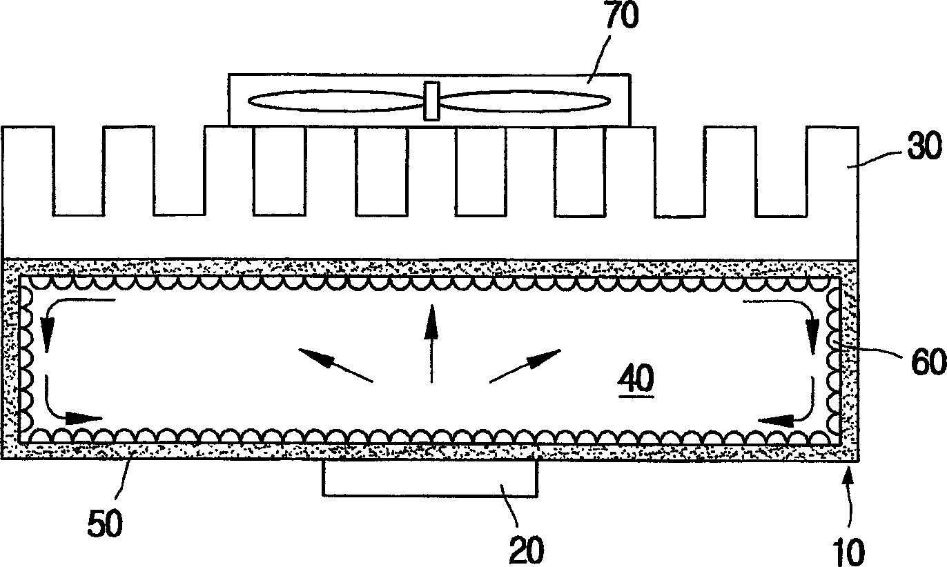
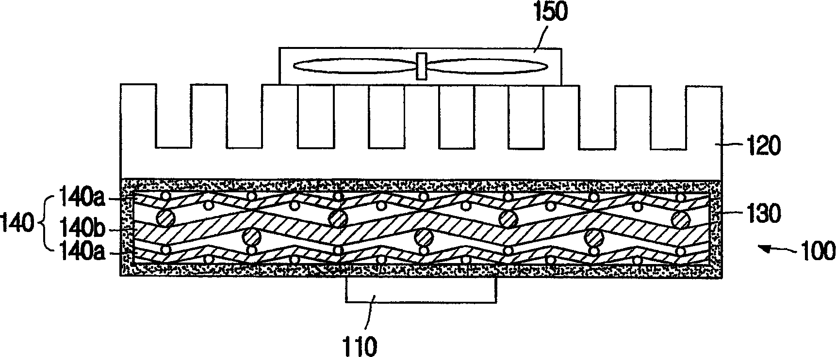
[0041] Such as figure 2 As shown, the flat heat transfer device 100 according to the first embodiment of the present invention includes a flat shell 130 and a mesh layer group 140, wherein the flat shell 130 is mounted on a heat source 110 and a heat emitting (heat emitting) unit (such as a radiator) 120 Between, and the mesh...


PUM

PropertyMeasurementUnit
Diameteraaaaaaaaaa

Abstract

Disclosed is a flat plate heat transfer device, which includes a thermally conductive flat case installed between a heat source and a heat emitting unit and containing a working fluid evaporated with absorbing heat from the heat source and condensed with emitting heat to the heat emitting unit; and a mesh layer aggregate installed in the flat case and having a structure that a fine mesh layer for providing a flowing path of liquid and a coarse mesh layer for providing a flowing path of liquid and a dispersion path of vapor simultaneously are laminated. On occasions, the coarse and the fine mesh layers are alternately laminated repeatedly, and the fine mesh layer is replaced with a wick structure. The coarse mesh layer is preferably a screen mesh layer with wire diameter of 0.2 mm ~ 0.4 mm and mesh number of 10 ~ 20. This device improves heat transfer performance.

Description

technical field [0001] The present invention relates to a flat plate heat transfer device capable of dissipating heat from a heat source by circulating a working fluid through evaporation and condensation, and more particularly relates to a flat plate heat transfer device having a thinner structure and good heat transfer and A flat plate heat transfer device with a heat dissipation structure. Background technique [0002] Recently, electronic devices such as notebook computers or PDAs have become smaller and thinner with the development of integration technology. Furthermore, while demands for high response and functional improvement of electronic devices increase, energy consumption tends to increase. Therefore, when the electronic equipment is in operation, the electronic components therein generate a large amount of heat, so various flat heat transfer devices are used to dissipate the heat to the outside. [0003] A traditional example of a conventional flat-plate heat ...

Claims


Application Information

Patent Timeline
IPC IPC(8): H05K7/20
CPCA41D20/00A42B1/004A42B1/18A42C5/02A42B1/0188
Inventor 李镕德吴玟正金炫兑张盛旭
Owner LG CABLE LTD (KR)
Why Eureka
Try Eureka