Assembling forming step pin axle

A combined molding and step pin technology, applied in bolts and other directions, can solve the problems of wasting materials, labor-intensive consumables, increasing the workload of lathes, etc., and achieve the effect of saving man-hours, improving service life, and saving production costs.

Inactive Publication Date: 2007-01-03
万俊
View PDF0 Cites 2 Cited by
  • Summary
  • Abstract
  • Description
  • Claims
  • Application Information

AI Technical Summary

Problems solved by technology

[0002] In all kinds of mechanical equipment, the pin shaft is used as a connecting support and fixed mechanical part. It is beneficial to the positioning of the pin shaft. Due to the existence of some steps, it is widely used to turn the material larger than the big end of the pin shaft on a lathe. This method will remove a lot of steel, waste materials, increase the workload of the lathe, and consume labor and consumables.

Method used


Image

  • Assembling forming step pin axle

Examples


Embodiment Construction

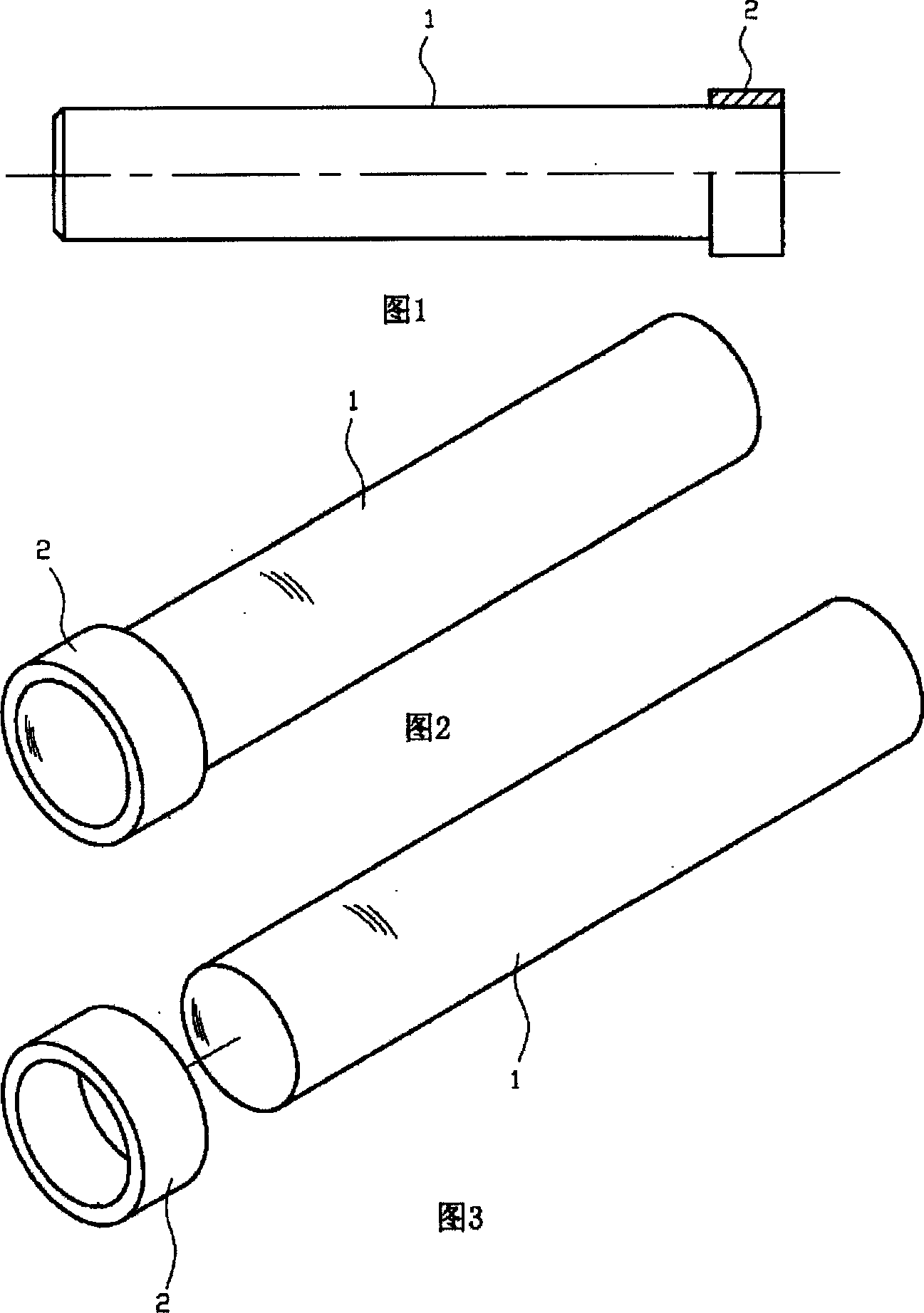
[0009] As can be seen from Figures 1 to 3, the feature of the present invention is that the step 2 larger than the diameter of the shaft body 1 is formed by assembling the annular step 2 with the shaft body 1 through interference fit.

[0010] The shaft body 1 of the present invention may be a cylinder made by cold drawing or turning. The step 2 can be installed at any position of the shaft body 1 . The step 2 may also be composed of multiple steps.

[0011] The process steps of the present invention are as follows: first, a round steel with a length of 6-8 meters and the outer diameter equal to the small end of the pin shaft is drawn by cold drawing, cut according to the designed length of the pin shaft, and then according to the design requirements of the pin shaft step, use a A steel pipe whose outer diameter is slightly larger than the outer diameter of the pin shaft step and whose inner diameter is slightly smaller than the outer diameter of the small end of the pin shaf...


PUM


Abstract

The present invention relates to various machine pin shafts, in particular it relates to a combination-formed stepped pin shaft. It is characterized by that the step greater than diameter of shaft body adopts shrink fit, it is made up by adopting circular ring step and shaft body through a certain assembling process. Said invention also provides its production method and concrete production steps.

Description

technical field [0001] The present invention relates to various mechanical pin shafts, in particular to combined formed stepped pin shafts. Background technique [0002] In all kinds of mechanical equipment, the pin shaft is used as a connecting support and fixed mechanical part. It is beneficial to the positioning of the pin shaft. Due to the existence of some steps, it is widely used to turn a material larger than the big end of the pin shaft on a lathe. This method turns off a large amount of steel, wastes materials, increases the workload of the lathe, and consumes labor and consumables. Contents of the invention [0003] The object of the present invention is to improve the shortcomings and problems existing in the background technology, and to provide a combination-shaped stepped pin shaft with advanced technology and practicality. [0004] The technical solution to realize the object of the present invention is to construct a pin shaft formed in a different body, w...

Claims


Application Information

Patent Timeline
Patent Type & Authority Applications(China)
IPC IPC(8): F16B19/02
Inventor 万俊
Owner 万俊
Why Eureka
Try Eureka