
Filter cleaning system for a vacuum cleaner

A technology for vacuum cleaners and filters, applied in the direction of suction filters, devices for cleaning filters, etc., which can solve the problem of no instructions on how to clean auxiliary filters

Inactive Publication Date: 2007-01-03
AB ELECTROLUX
View PDF1 Cites 12 Cited by
  • Summary
  • Abstract
  • Description
  • Claims
  • Application Information

AI Technical Summary

Problems solved by technology

The obvious disadvantage of the first device is that two electric motors are required, and in the second there is no indication how to clean the auxiliary filter

Method used


Image

  • Filter cleaning system for a vacuum cleaner
  • Filter cleaning system for a vacuum cleaner
  • Filter cleaning system for a vacuum cleaner

Examples


Embodiment Construction

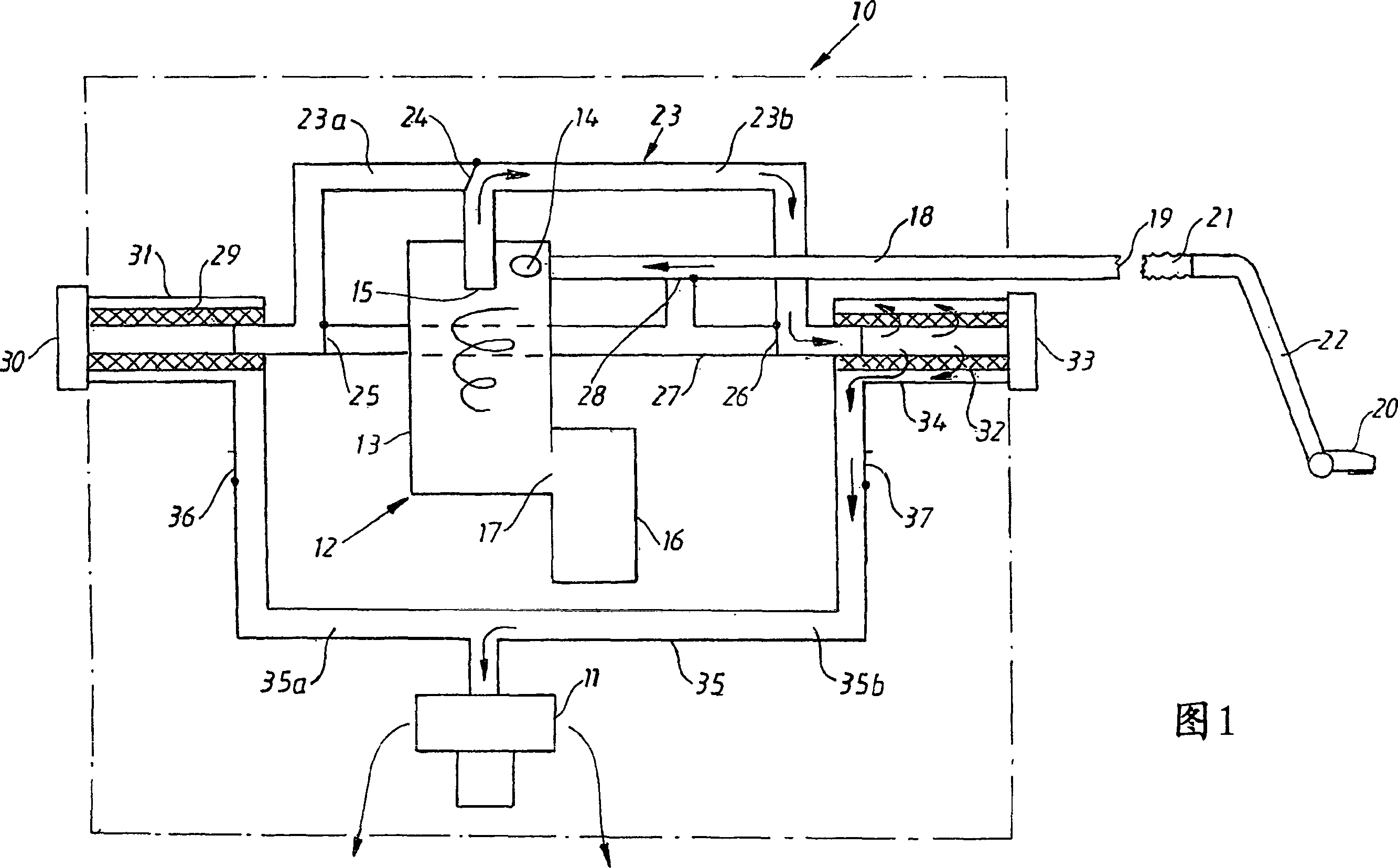
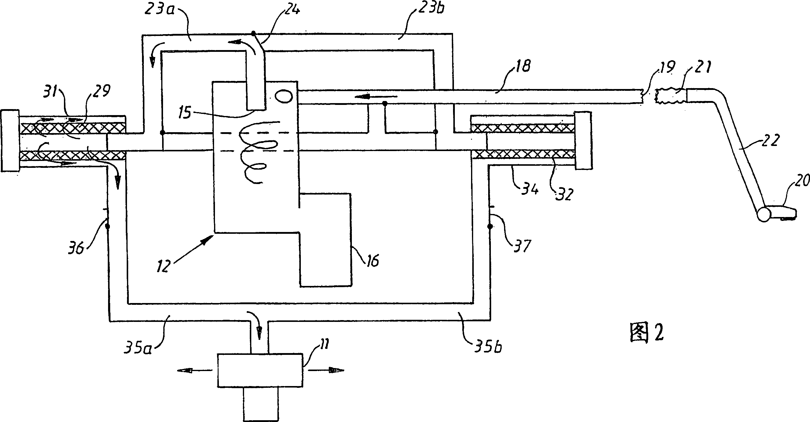
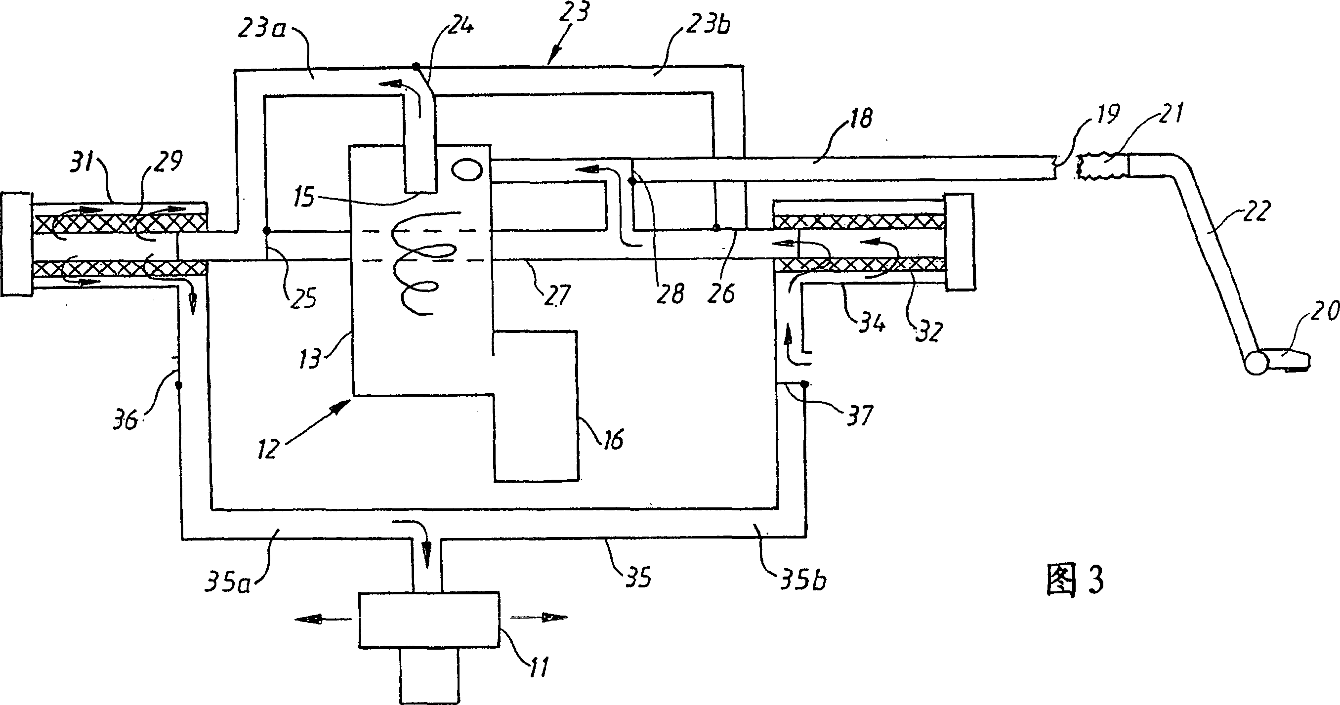
[0010] FIG. 1 schematically shows a vacuum cleaner body 10 enclosing a single vacuum source, such as a fan unit 11 , and a dust separation unit 12 . The dust separation unit 12 is of the so called cyclone type and comprises a circular chamber 13 provided with a tangential inlet 14 for dusty air and a central outlet 15 for clean air. Owing to the air flow, a vortex is generated in the chamber 13 and the dust particles are separated from the air flow by the action of the centrifugal force and enter the dust collection container 16 via the opening 17 .

[0011] The inlet 14 is connected via a channel 18 to an opening 19 in the vacuum cleaner body which is connectable to the vacuum cleaner mouth 20 via a hose 21 and a tube shaft 22 in a conventional manner. The central cyclone outlet 15 is connected to the channel 23 via a valve 24 so that the gas flow can be directed to either the first part 23a or the second part 23b of the channel 23 . Said portions 23a and 23b are connected v...


PUM


Abstract

The invention relates to a vacuum cleaner comprising a body with a vacuum source (41). The vacuum cleaner is provided with at least two filter spaces (53, 59), a first filter holder for the first filter device (52) in the active cleaning position and a second holder for the aforementioned filter unit in the standby, non-cleaning position The same filter unit or a second filter unit (58).

Description

technical field [0001] The present invention relates to a vacuum cleaner comprising a body having a vacuum source. Background technique [0002] Conventional vacuum cleaners generally fall into two distinct categories called canister vacuums and upright vacuum cleaners. Canister vacuum cleaners include a housing that encloses an electric fan unit that generates an airflow from the mouth of the vacuum cleaner through the tube shaft and hose and further through a separation system consisting of air that reaches the fan and exits the housing to ambient air The porous bag that collected the dust before. Upright vacuum cleaners differ from canister vacuum cleaners by the elimination of the shaft and hose, and by the fact that the mouth, usually provided with rotating brushes, is pivotally attached to the vacuum cleaner housing. The housing encloses the fan unit and the air permeable dust bag, and has a handle to move the entire vacuum cleaner over the floor. [0003] In order ...

Claims


Application Information

Patent Timeline
IPC IPC(8): A47L9/20A47L9/16A47L
Inventor L·门里克安娜-卡琳·格雷F·洛夫内斯H·米耶法尔克M·扬松安娜-卡琳·特吕德高M·贝林H·霍尔姆L·梅恩博里
Owner AB ELECTROLUX
Learn More