Pipeline ring hollow cleaning assembly

A technology for cleaning components and annulus, which is applied in the direction of cleaning hollow objects, cleaning methods and tools, chemical instruments and methods, etc. It can solve the problems of no sealing function, lack of annulus cleaning equipment, and inconvenient maintenance of pipelines, etc., so as to achieve simple operation , Simple structure, easy installation

Inactive Publication Date: 2007-01-10
CHINA NAT OFFSHORE OIL CORP +2
View PDF0 Cites 2 Cited by
  • Summary
  • Abstract
  • Description
  • Claims
  • Application Information

AI Technical Summary

Problems solved by technology

For this reason, there is such a problem: for double-layer pipelines, the annulus is filled with fillers, but it does not have a sealing function, so the fillers in the annulus must be cleaned before the annulus is sealed. , so that the end of the inner tube protrudes outside the outer tube
Therefore, in the existing techn...

Method used


Image

  • Pipeline ring hollow cleaning assembly
  • Pipeline ring hollow cleaning assembly
  • Pipeline ring hollow cleaning assembly

Examples


Embodiment Construction

[0023] In order to have a clearer and more comprehensive understanding of the characteristics, effects and technical objectives of the annulus cleaning assembly of the present invention, the specific embodiments of the present invention will now be described with reference to the accompanying drawings.

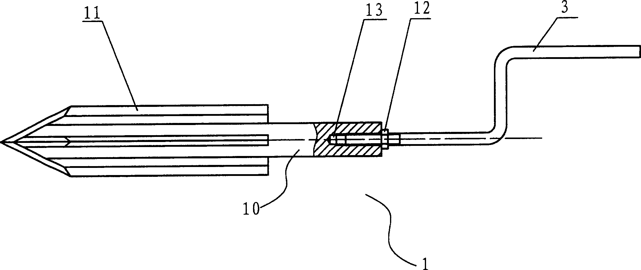
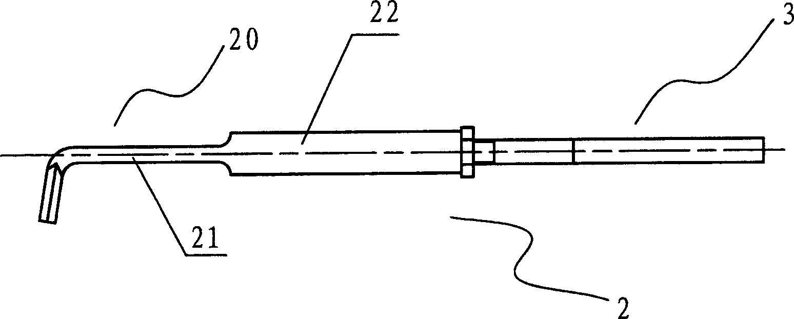
[0024] See figure 1 with 3 , which are respectively schematic diagrams of embodiments of the crushing tool and the clearing tool in the pipeline annulus cleaning assembly of the present invention. The pipeline annulus cleaning assembly of the present invention includes a crushing tool 1 and a cleaning tool 2. The crushing tool 1 is used to initially crush the filling, and the cleaning tool 2 is used to plan out the filling and further clean out the pipe wall. filling on top.

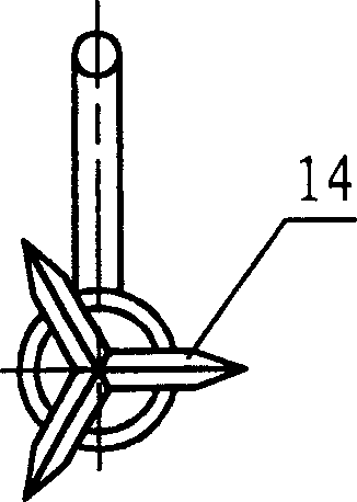
[0025] See figure 1 with 2 The crushing tool 1 in the pipeline annulus cleaning assembly of the present invention includes a multi-edged cutter head 11 with a tapered front end and a handle 3, and th...


PUM


Abstract

A pipe clearing component includes a mashing tool and a clearing out tool, in which, the mashing tool is composed of a multi-ridge cutter head and a handle and the clearing out tool includes toothed harrow and a handle, which smashes fillers firstly by the mashing tool then uses the clearing out tool to dig out the fillers.

Description

technical field [0001] The invention relates to a pipeline annulus cleaning tool, in particular to a pipeline annulus cleaning assembly for cleaning fillers in the annulus. Background technique [0002] Pipeline transportation is an important mode of transportation, especially the transportation of oil and natural gas. With the continuous expansion of energy demand, the role of pipeline transportation has become increasingly prominent. In pipeline technology, pipeline plugging is an essential technology after an accident or maintenance in pipeline transportation. [0003] In the current maintenance operation method, it is very common to cut off the damaged part and replace it with a new pipeline when the subsea pipeline is repaired. If the pipeline is damaged so badly that it cannot be supplied and transported normally, it needs to be shut down for maintenance. At this time, the maintenance process is carried out in the dry cabin, so the cabin must be filled with a certai...

Claims


Application Information

Patent Timeline
IPC IPC(8): B08B9/36
Inventor 陈应华张宏房晓明赵宏林喻开安李杰
Owner CHINA NAT OFFSHORE OIL CORP
Why Eureka
Try Eureka