
Method and apparatus for carrying a plate-shaped part

A technology for handling devices and objects, which is applied in the direction of transportation and packaging, conveyor objects, chucks, etc. It can solve the problems of difficult position control, large-scale handling devices, and large handling loads, and achieve the effect of less contact and less deflection

Inactive Publication Date: 2007-01-10
TOSHIBA MASCH CO LTD
View PDF1 Cites 14 Cited by
  • Summary
  • Abstract
  • Description
  • Claims
  • Application Information

AI Technical Summary

Problems solved by technology

[0005] However, if the fingers, etc. on which the flat-shaped conveyed object is placed are large, the conveying load of the conveying device such as a robot arm will increase, and it will be difficult to perform position control quickly and accurately, resulting in problems such as increasing the size of the conveying device.

Method used


Image

  • Method and apparatus for carrying a plate-shaped part
  • Method and apparatus for carrying a plate-shaped part
  • Method and apparatus for carrying a plate-shaped part

Examples


Embodiment

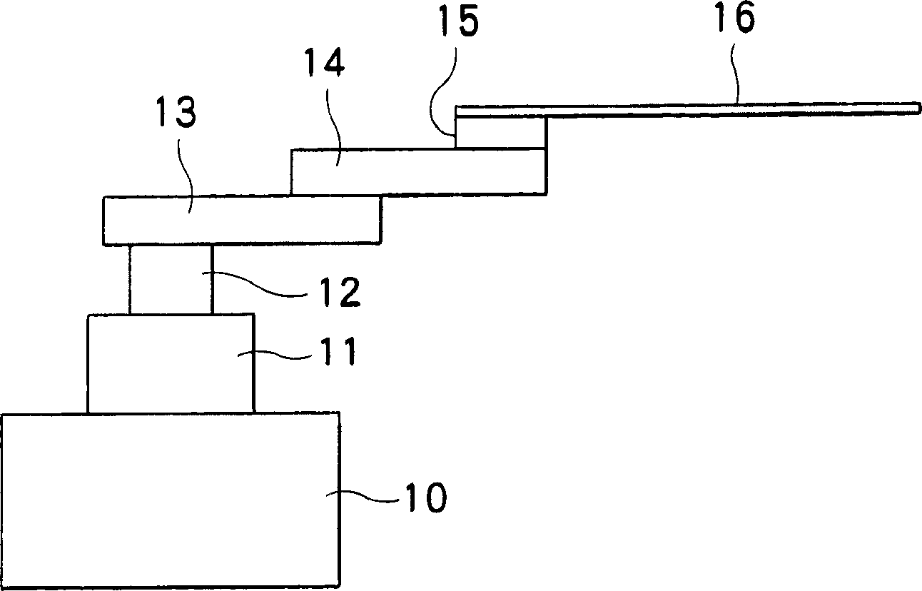
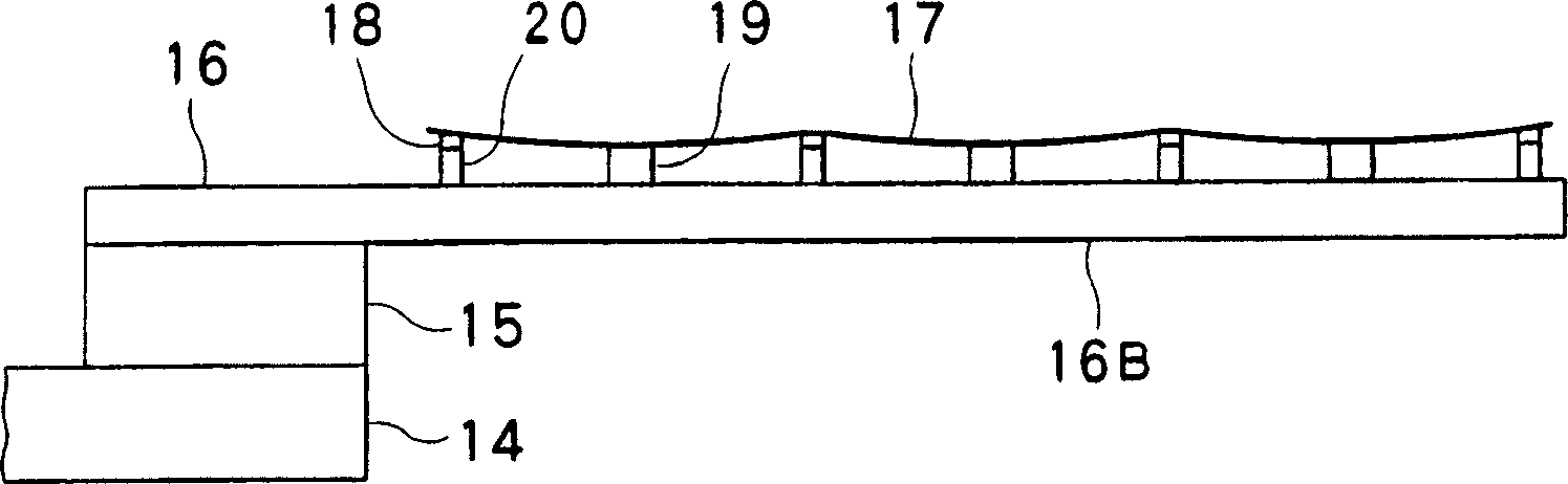
[0053] use Figure 2 to Figure 3 As shown in the figure, the illustrated fork 16 holds a glass plate-shaped carrier 17 of the following size and thickness. among them,

[0054] The size of the flat conveying object 17: length×width×thickness=1500mm×1000mm×1mm

[0055] Interval between fingers 16A and 16B = 600mm

[0056] The distance between the gasket 18 and the suction part 19 = 240mm

[0057] The height difference between the pad 18 and the suction part 19 during suction = 2mm

[0058] At this time, the amount of deflection in the width direction of the flat conveyed object 17 = 8 mm.

[0059] In contrast, as Comparative Example 1, when the suction portion 19 is replaced with a pad 18, that is, all the pads 18 are the same height, and the other conditions are the same as in the above-mentioned Example 1, the amount of deflection in the width direction is It is 9mm.

[0060] use Figure 4 to Figure 5 As shown in the figure, the illustrated fork 26 holds a glass plate-shaped carri...


PUM


Abstract

The invention provides a flat material conveying method and its device capable of miniaturizing a holder part such as a finger and capable of accurately conveying flat conveyed materials by restricting bend of the flat conveyed material due to dead wight thereof, while restricting a contact with the flat conveyed material. The flat conveyed material 17 is held by a holding part formed of a pad 18 and a suction part 19. The pad 18 abuts on a lower surface of the flat conveyed material 17 to support it. The suction part 19 is arranged between the pad 18, and height of the pad 18 is set low in the suction condition to vacuum-suck the lower surface of the flat conveyed material 17. The flat conveyed material 17 is thereby forcibly bent to reduce the amount of bend in a direction along an angle and / or a valley of the bend.

Description

Technical field [0001] The present invention relates to a method and an apparatus for conveying a flat conveyed object such as a glass substrate for a liquid crystal panel, and particularly relates to the conveying of a flat conveyed object in which the flat conveyed object is placed approximately horizontally and the lower or upper surface is maintained for conveyance. Method and device. Background technique [0002] Such flat conveyed objects are generally stored in a multi-layer pallet, are sequentially conveyed to the processing device by a conveying device such as a robot, and are returned to the pallet after being processed by the processing device. The conveyance of this flat conveyed object is often carried out by using a holding portion composed of a fork-shaped finger disclosed in JP 11-322069 A. [0003] When the conveyed object has a large area like a glass substrate for a large liquid crystal panel and has a thin thickness, the amount of deflection increases due to i...

Claims


Application Information

Patent Timeline
IPC IPC(8): B65G49/00B65G49/06B25J15/00
CPCB25J15/06B65G49/06H01L21/677
Inventor 小椋胜仁根岸祐司
Owner TOSHIBA MASCH CO LTD
Features
  • Generate Ideas
  • Intellectual Property
  • Life Sciences
  • Materials
  • Tech Scout
  • Unparalleled Data Quality
  • Higher Quality Content
  • 60% Fewer Hallucinations
Learn More