Linear sliding rail containing lubricating retaining device

A technology of linear slides and retaining devices, applied in the direction of linear motion bearings, bearings, shafts and bearings, etc., can solve the problems of deterioration and failure, reduction of thrust size, relaxation, etc., to achieve long-term stable thrust, easy assembly, and simple structure Effect

Active Publication Date: 2007-01-10
HIWIN TECH
View PDF3 Cites 5 Cited by
  • Summary
  • Abstract
  • Description
  • Claims
  • Application Information

AI Technical Summary

Problems solved by technology

[0004] A. A spring mechanism is installed in the lubricating oil tank, and the spring mechanism inside is used to push and squeeze the oily sponge to keep the oily sponge in effective contact with the slide rail. The disadvantage is that the structure is complex and inconvenient to assemble, and the spring has stress and wear. Gradual relaxation, elastic fatigue, and unstable lubrication thrust (patent number: US5547285)
[0005] B. Install a ㄇ-shaped spring piece in the lubricating device, use this ㄇ-shaped spring piece to push the sponge containing lubricating oil from the outside to the inside, and keep the sponge containing lubricating oil in effective contact with the slide rail. The disadvantage is that the thrust will vary From large to small, its elastic force will gradually relax with the wear of the lubricating oil sponge, and there will be elastic fatigue problems (patent number: US 6672764)
[0006] C. Elastic rubber is installed in the lubricating device, and the elastic rubber is used to push the lubricating sponge components, which can also maintain the effective contact between the lubricating oil components and the slide rail, but its disadvantages also have the problems of gradual relaxation of thrust and elastic fatigue, and weather resistance Poor performance, easy to cause deterioration and failure due to different climates (patent number: US 6123457)
[0007] It can be seen from the above products that in the past, when using the lubrication system of the linear mechanism, it must be cleaned, replaced or repaired within a certain period of time, but it cannot maintain a stable lubrication thrust for a long time. Sincerely looking forward to striving for the goal of improvement

Method used


Image

  • Linear sliding rail containing lubricating retaining device
  • Linear sliding rail containing lubricating retaining device
  • Linear sliding rail containing lubricating retaining device

Examples


Embodiment Construction

[0043] Relating to the invention of the present application for achieving the above-mentioned purpose, the highly technical ideas and means adopted, hereby enumerate a preferred embodiment and cooperate with Fig. 1-4 formula to describe in detail as follows, believe that the purpose, characteristics and other advantages of the invention of the application, A deep and specific understanding can be obtained from it.

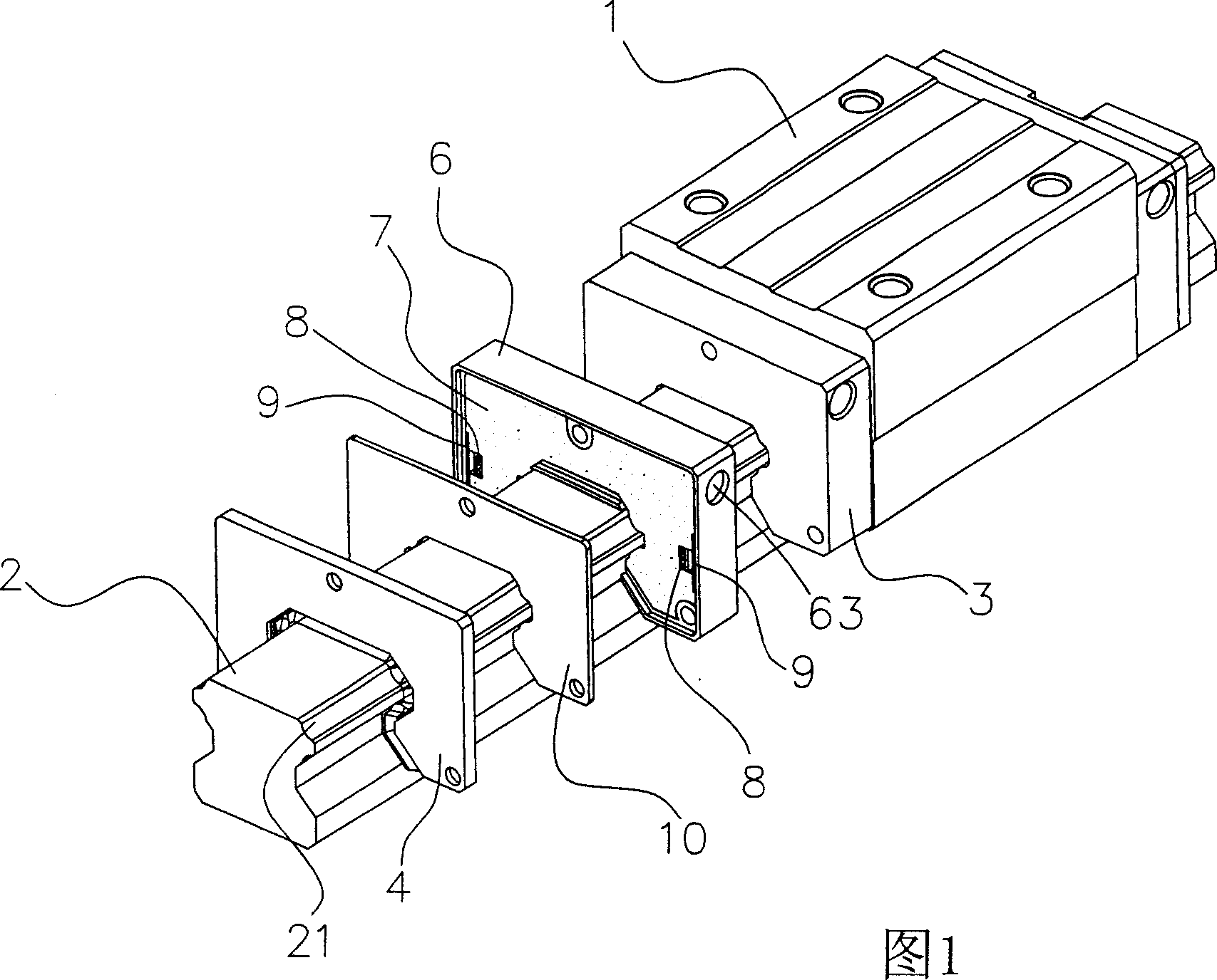
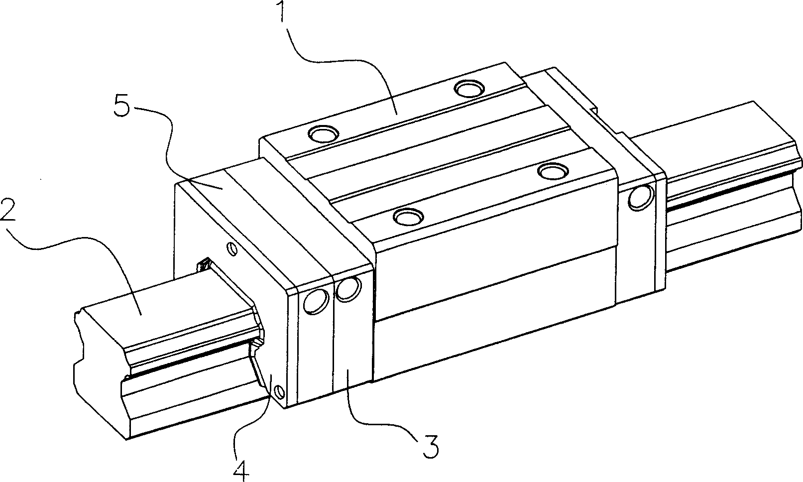
[0044] The linear slide rail containing the lubricating retaining device of the present invention includes a slide block 1, a slide rail 2 provided with a bead groove 21, two end covers 3, two oil wipers 4, and a lubricating device 5 (please refer to figure 2 );

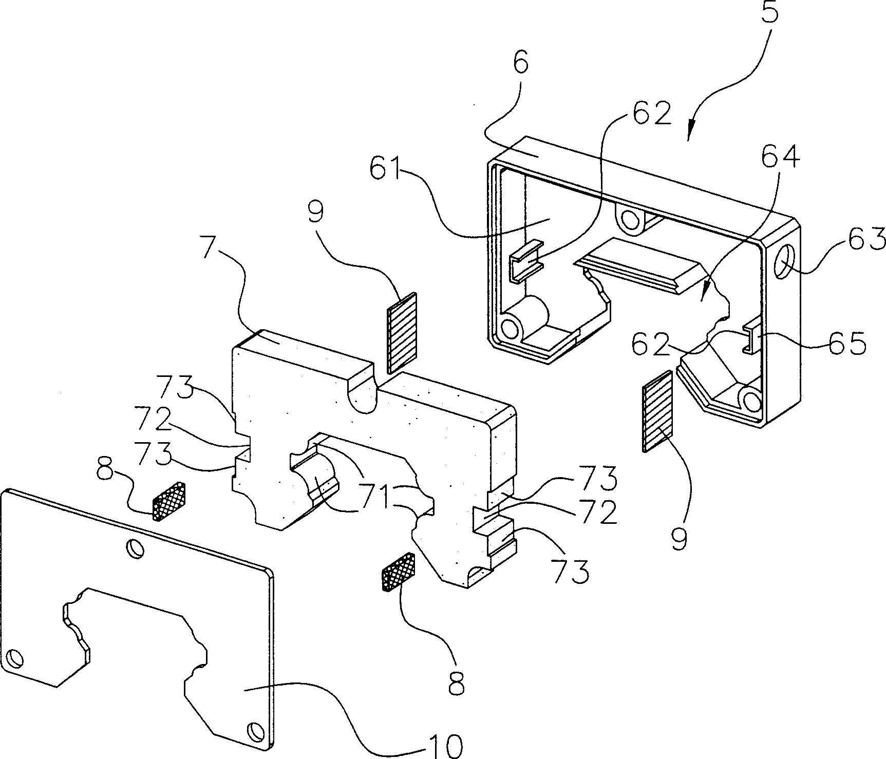
[0045] And this lubricating device 5 is assembled between the end cap 3 and the oil scraper 4 at the two ends of the slide block 1, and the lubricating device 5 is composed of a supporting shell 6, a lubricating oil assembly 7, two magnets 8, two metal magnetic parts 9 and a support The combined cover 10...


PUM


Abstract

The invention is a truly original linear sliding rail comprising lubrication holder, applied in the lubricating device at the end of a slide block, and it comprises: casing, lubrication-containing component, magnetic piece and magnet, and uses the magnet to produce attraction corresponding to the magnetic piece (such as metallic magnetic piece and metallic sliding rail) to make the magnet or magnetic piece to push the lubricant-containing component so as to keep contact energy between the lubricant-containing component and the sliding rail, thus able to continuously supply lubricant from the lubricant-containing component to the surface of ball groove of the sliding rail to solve the problem of bad lubrication caused by abrasion of the lubricant-containing component and achieve a long-term maintenance-free effect

Description

technical field [0001] The present invention provides a lubricating and maintaining device in a linear assembly, which uses the principle of magnetic induction to allow the linear slide rail to wear and tear the lubricating oil-containing assembly, and the lubricating oil-containing assembly can still continuously transmit the lubricating oil to the ball of the slide rail ditch surface. Background technique [0002] Due to the continuous development and improvement of precision feed systems, linear slide rail technology and its products have become the most important part of many precision machines, and various linear mechanism products have widely entered human life, processing plants and high-tech equipment Although the development of linear slide rail technology is very rapid, consumers still need continuous improvement of technology, so there are many problems that linear products (such as: linear slide rail) still need to be developed, and related technology industries ...

Claims


Application Information

Patent Timeline
Patent Type & Authority Applications(China)
IPC IPC(8): F16C29/06
Inventor 许新村谢敏耀
Owner HIWIN TECH
Why Eureka
Try Eureka