Flat-type cold cathode fluorescent lamp

A cold-cathode fluorescent lamp, flat type technology, applied in the direction of discharge lamps, gas discharge lamps, parts of gas discharge lamps, etc., can solve the problems of uneven brightness of the light-emitting surface, reduced luminous flux, etc., to suppress uneven brightness and improve luminous flux Effect

Inactive Publication Date: 2007-01-10
HARISON TOSHIBA LIGHTING CORP
View PDF3 Cites 0 Cited by
  • Summary
  • Abstract
  • Description
  • Claims
  • Application Information

AI Technical Summary

Problems solved by technology

If the inner diameter of the end in the long-axis direction in the discharge space is too small, there is a problem that when the lamp is turned on, the anode light column hardly diffuses in the long-axis direction, resulting in uneven brightness on the light-emitting surface, and the overall luminous flux Obvious reduction

Method used


Image

  • Flat-type cold cathode fluorescent lamp
  • Flat-type cold cathode fluorescent lamp
  • Flat-type cold cathode fluorescent lamp

Examples


Embodiment Construction

[0042] Hereinafter, embodiments of the present invention will be described in detail with reference to the drawings.

[0043] (first embodiment)

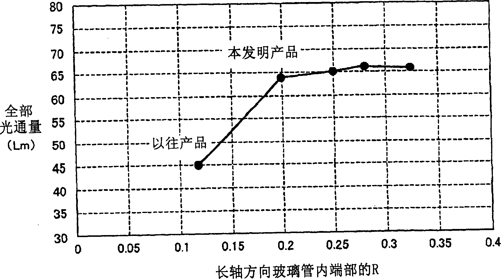
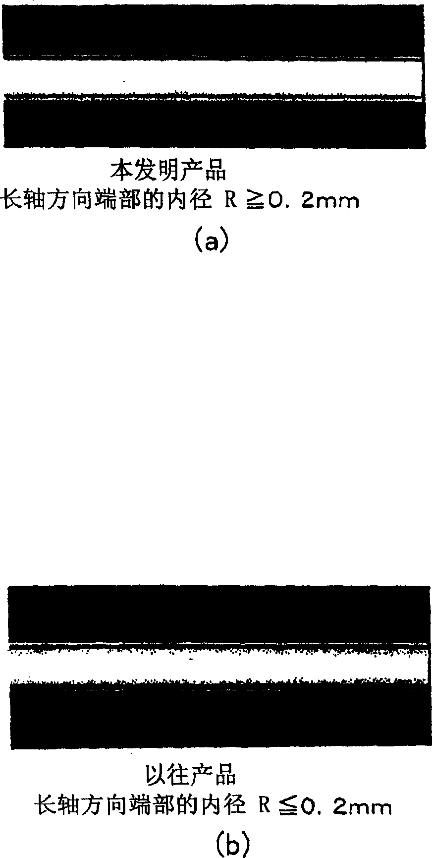
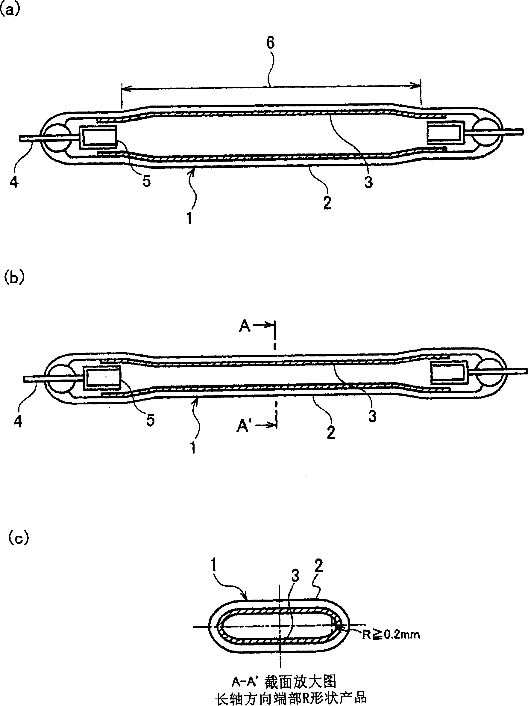
[0044] In a first embodiment of the present invention, in the flat cold cathode fluorescent lamp, the inner diameter of the longitudinal end in the discharge space is R≧0.2 mm.

[0045] figure 1 The short axis direction of the flat processed part of the flat cold cathode fluorescent lamp is constant, and the inner diameter (radius) R of the R part at the end of the long axis direction in the discharge space is changed, and it is confirmed that the brightness unevenness of the light emitting surface and the entire lamp Limit value for luminous flux reduction. If the inner diameter of the longitudinal end in the discharge space is R≦0.2 mm as in the conventional case, it is found that the anode beam is difficult to spread to the longitudinal end, and the total luminous flux of the lamp is significantly reduced.

[0046] figure 2...


PUM


Abstract

A flat-type cold cathode fluorescent lamp is provided to suppress luminance speck on a light emitting side thereof by diffusing effectively a positive column to an end of a long diameter direction of a discharge space. A sectional shape of an internal discharge space is formed with an elliptic having a long diameter and a short diameter or a flat glass tube(2). A phosphor coating layer(3) is formed on an inner surface of the glass tube. The internal discharge space of the glass tube is filled with mercury and rare gas. Both ends of the glass tube are connected with lead lines(4). The lead lines are connected with electrodes(5). An inside diameter of an end part in the long diameter direction within the discharge space of the glass tube is more than 0.2mm.

Description

technical field [0001] The present invention relates to a flat type cold cathode fluorescent lamp. Background technique [0002] Figure 19 Shown is a structural diagram of a conventional flat cold-cathode fluorescent lamp. exist Figure 19 Among them, the conventional flat cold cathode fluorescent lamp 21 is constructed in such a way that the cross-sectional shape of the internal discharge space of its glass tube 22 is shaped into an oval or flat shape at least defined by the major axis and the minor axis. A fluorescent film 23 is formed on the inner surface, mercury and rare gas (neon, argon) are sealed in the internal discharge space of the glass tube 22 as a discharge medium, and electrodes 25 connected to the lead-in wires 24 hermetically sealed at both ends of the glass tube 22 are installed. , but there is no special regulation on the inner diameter of the end in the longitudinal direction of the discharge space. [0003] In the conventional flat cold-cathode fluore...

Claims


Application Information

Patent Timeline
Patent Type & Authority Applications(China)
IPC IPC(8): H01J61/33H01J61/00
CPCA41B11/00A41B2400/34A41B2400/60A41B2500/10D01F1/103D02G3/449D03D1/00D04B1/26D10B2501/021
Inventor 石山政之池田达也木村吉博菅原匡道富田保男
Owner HARISON TOSHIBA LIGHTING CORP
Why Eureka
Try Eureka