
Electromagnetic retarder comprising means ensuring ventilation

A technology of electromagnetic reducer and reducer, which is applied in the direction of cooling/ventilation device, electric brake/clutch, electromechanical device, etc. It can solve the problems of random air flow path, fan energy consumption, non-optimization, etc., and achieve increased performance , reduce the heat exchange surface, reduce the effect of volume and size

Inactive Publication Date: 2007-01-10
TELMA
View PDF4 Cites 14 Cited by
  • Summary
  • Abstract
  • Description
  • Claims
  • Application Information

AI Technical Summary

Problems solved by technology

These fans are coupled to a shaft or rotor, however, the path of the airflow it creates is random, unobstructed, and non-optimized
[0012] [12] Furthermore, these fans consume a lot of energy

Method used

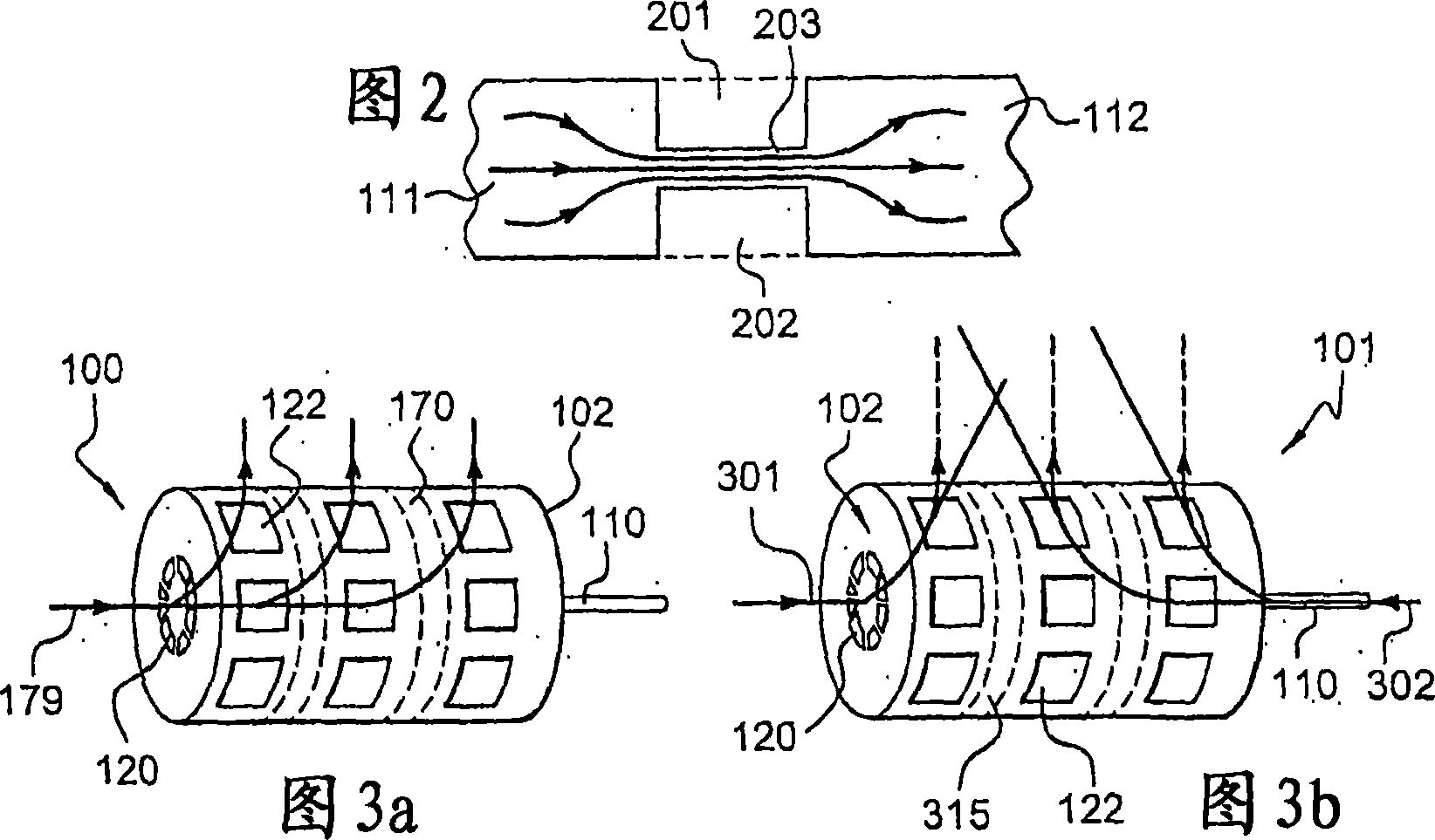

Image

  • Electromagnetic retarder comprising means ensuring ventilation
  • Electromagnetic retarder comprising means ensuring ventilation
  • Electromagnetic retarder comprising means ensuring ventilation

Examples


Embodiment Construction

[0048] [48] ​​Components common to several figures retain the same reference numerals.

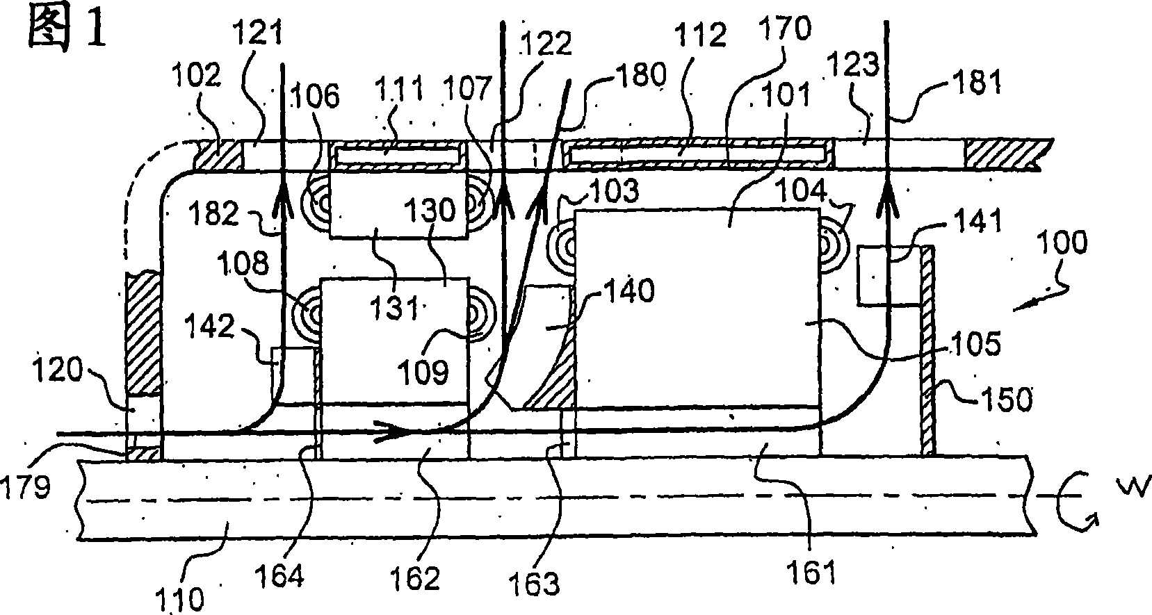
[0049] [49] FIG. 1 is an axial sectional view of half of a speed reducer 100 of the present invention. The electromagnetic reducer 100 has a housing 102 supporting a stator 170, a shaft 110, a rotor 101 coupled with the shaft 110, an electric coil (not shown) supported by the rotor 101 having a main body, and rotating with the shaft 110 The coupled blades 140-142, and a generator powering the here axially elliptical coils.

[0050] [50] The housing 102 has holes or openings 120-123 which, in combination with the vanes 140-142, allow good heat dissipation especially at the coils. The holes 120-123 and the vanes 140-142 belong to a ventilation means. The hollow housing 102 is shaped to fit preferably elastically on a fixed part of the vehicle. The shaft 110 has an axis of symmetry, which is the axis of the rotor 101 .

[0051] [51] Here, the stator 170 coincides with the housing 102 made...


PUM


Abstract

The invention essentially consists of a retarder(100) comprising a stator(170) and / or a housing(102) surrounding or encasing a rotor(101), means(140-142) for producing an air current and at least one inlet(120) enabling said air current to enter and at least one outlet(120) used to evacuate said air current. The outlet(121-123) is created between to cooling chambers(111-112) or through several cooling chambers which are borne by the housing and / or stator of the retarder.

Description

technical field [0001] [01] The invention relates to an electromagnetic retarder having means for ensuring ventilation. The invention aims to facilitate the cooling of such a reducer, especially its coils. The invention also aims to reduce the noise generated during the operation of the reducer. The invention is particularly advantageous, but not limiting, for slowing the motion of load-carrying vehicles such as trucks or buses. Background technique [0002] [02] Generally speaking, the electromagnetic reducer helps the vehicle to brake, making it safer, more reliable and more durable. The electromagnetic speed reducer has at least one stator and at least one rotor. The stator is connected to the vehicle's transmission case or transaxle case. In this case, the drive shaft is not separated to install the reducer. When the transmission shaft is not separated, it is called a Focal (registered trademark) reducer. In other embodiments, the stator is fixed to the chassis of ...

Claims


Application Information

Patent Timeline
Patent Type & Authority Applications(China)
IPC IPC(8): H02K9/06H02K5/20H02K7/20H02K49/04
CPCH02K1/32H02K49/043H02K5/20H02K7/20H02K9/06H02K5/207H02K5/203
Inventor C·瓦西莱斯科
Owner TELMA
Learn More