
Communication coding system and method based on optical fibers and power lines

A coding system and power line technology, applied in the field of communications, can solve problems such as broadcast storms, users competing for bandwidth, and wiring zero line sharing, etc., and achieve the effect of solving current loop problems, achieving division, isolation and spreading.

Inactive Publication Date: 2017-05-17
重庆金燕巢科技有限公司
View PDF3 Cites 4 Cited by
  • Summary
  • Abstract
  • Description
  • Claims
  • Application Information

AI Technical Summary

Problems solved by technology

[0003] However, after practice, it is found that whether it is a residential building, a shopping mall, a hotel, an office building, etc., due to the problem of sharing the zero line in the wiring of the power system in our country, the power carrier technology combining optical fiber and power line is used under high-speed broadband (above 20M). It solves the problem of competing for bandwidth with each other, resulting in the widespread occurrence of broadcast storms
Broadcast storms not only exist in power carrier technology, but also in the GPON fiber-to-the-home technology of the four major operators. This drawback has always been a technical problem in the communication industry, and has always troubled operators and the majority of network users.

Method used


Image

  • Communication coding system and method based on optical fibers and power lines
  • Communication coding system and method based on optical fibers and power lines
  • Communication coding system and method based on optical fibers and power lines

Examples


example 2

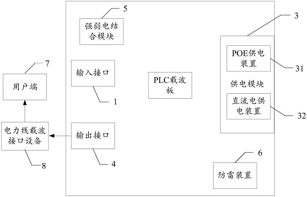
[0063] As a specific example 2 of the present invention, the communication coding system is composed of a first DC coil arranged on a DC board and replaced by a second DC coil, and the first DC coil and the second DC coil are arranged on the DC board. The input interface is connected to the air switch of the electric meter, and the input interface is used to access the Ethernet or optical fiber signal, and the Ethernet or optical fiber signal is connected to the FTTH, OLT, ONU and DED carrier board. FTTH, OLT, ONU, and DED carrier boards are connected to DC through data converters. OEO and DED carrier boards use OFDM orthogonal frequency division multiplexing technology to connect Ethernet or optical fiber signals to DC boards in the form of carriers through modulation and demodulation. first DC coil. The DC board is to combine the carrier signal modulated by FTTH, OLT, ONU and DED carrier board through FTTH, OLT, ONU and DED signal line in a direct current way with the fire a...


PUM


Abstract

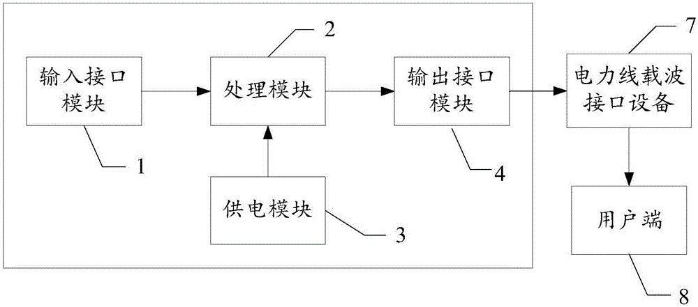
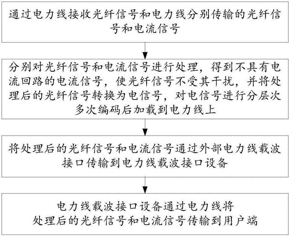
The invention relates to a communication coding system and method based on optical fibers and power lines. The communication coding system includes an input interface module, a processing module, a power supply module, an output interface module, power line carrier interface equipment and a user terminal; the input interface module is used for receiving optical fiber signals and current signals transmitted by the optical fibers and the power lines respectively and sending the optical fiber signals and the current signals to the processing module; the processing module is used for processing the optical fiber signals and the current signals respectively, converting the processed optical fiber signals into electric signals, conducting hierarchical multiple coding on the electric signals and then loading the result electric signals to the power lines; the output interface module is used for transmitting the processed optical fiber signals and the electric signals to the power line carrier interface equipment through an external power line carrier equipment interface; the power line carrier interface equipment is used for transmitting the processed optical fiber signals and the current signals to the user terminal. A hierarchical multiple coding networking technology is adopted, a broadcasting storm is solved, and the situation that users do not interfere with one another on the Internet under the high-speed broadband is achieved.

Description

technical field [0001] The invention relates to the technical field of communication, in particular to a communication encoding system and method based on optical fiber and electric power line. Background technique [0002] In recent years, the power carrier technology combined with optical fiber and power line has become a brand new network access technology. Its advantages and characteristics are: 1) Using power line as the carrier, it provides the best home solution for high-speed broadband "last 100 meters" , PLC can transmit various data, voice and image, etc., and is generally applicable to networking and high-speed Internet access in residential quarters, institutions, schools and other places. Photoelectric broadband is flexible and easy to use. Users can enjoy high-speed network access, browse the web, make VOIP calls and watch online TV and movies through TV at any socket with power outlets in the room, so as to realize the "multi-network integration" of data, voi...

Claims


Application Information

Patent Timeline
Patent Type & Authority Applications(China)
IPC IPC(8): H04B3/54
CPCH04B3/54H04B3/542H04B3/544
Inventor 季洪曼廖大鑫
Owner 重庆金燕巢科技有限公司
Learn More