Discharging structure of reciprocating rotary compressor

A rotary compressor and duplex technology, applied in the field of gas discharge structure, can solve the problems of increasing the size of the compressor, increasing the cost of materials, inconvenience, etc., and achieve the effect of reducing the number and cost of materials

Inactive Publication Date: 2007-01-17
LG ELECTRONICS (TIANJIN) APPLIANCES CO LTD
View PDF0 Cites 1 Cited by
  • Summary
  • Abstract
  • Description
  • Claims
  • Application Information

AI Technical Summary

Problems solved by technology

[0012] However, in the existing compound rotary compressor as described above, in addition to forming the gas holes 22b and 21b in the auxiliary bearing 22 and the second cylinder 21 respectively, it is also necessary to install a separate second muffler 25 under the auxiliary bearing 22 , thus increasing the material cost and increasing the size of the compressor by an amount equal to the height of the second muffler 25
[0013] This shows that the above-mentioned existing compound rotary compressor obviously still has inconvenience and defects in structure and use, and needs to be further improved urgently.
In order to solve the problems existing in the compound rotary compressor, the related manufacturers have tried their best to find a solution, but no suitable design has been developed for a long time, and the general products have no suitable structure to solve the above problems. Obviously, it is a problem that relevant industry players are eager to solve.

Method used


Image

  • Discharging structure of reciprocating rotary compressor
  • Discharging structure of reciprocating rotary compressor
  • Discharging structure of reciprocating rotary compressor

Examples


Embodiment Construction

[0036] In order to further explain the technical means and effects that the present invention adopts to achieve the intended purpose of the invention, below in conjunction with the accompanying drawings and preferred embodiments, the specific implementation, structure, Features and their functions are described in detail below.

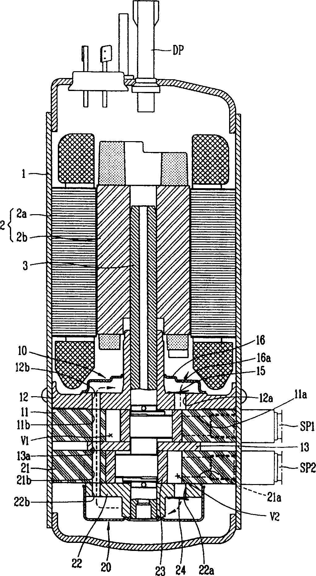
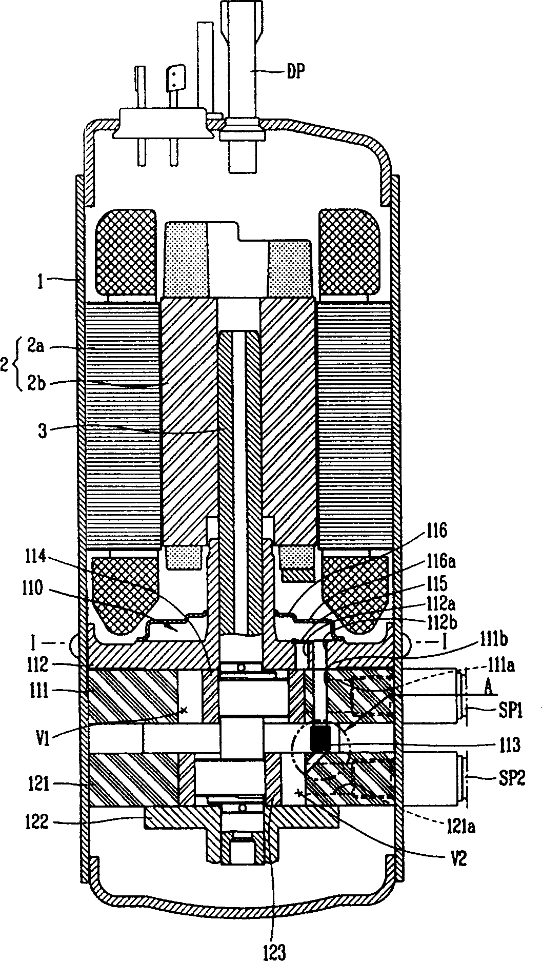
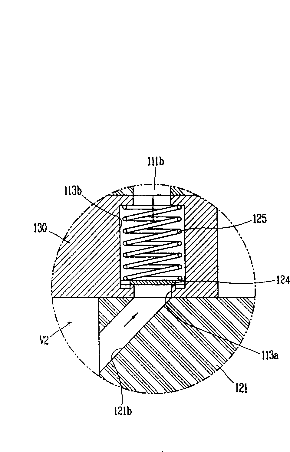
[0037] figure 2 It is a sectional view of a certain embodiment of the compound rotary compressor applicable to the present invention, image 3 is true figure 2 Part "A" in the enlarged detail diagram, Figure 4 is along figure 2 A cross-sectional view of the "I-I" line in, Figure 5a and 5b It is a schematic diagram of the discharge process of the refrigerant in each compressor unit in the compound rotary compressor to which the present invention is applied.

[0038] As shown in the figure, the compound rotary compressor applicable to the present invention includes a motor part 2 installed on the upper side of the casing 1 for generating rota...


PUM


Abstract

This is a kind of air discharging structure of twin rotating compressor. It includes the first and second air cylinders, which absorb and compress refrigerants; intermediate bearing separating the inner space of the two air cylinders; main bearing and assistant bearing respectively setting at upper and lower sides of the air cylinders at both sides. They not only seal the inner space of two air cylinders, but also support the rotating shaft, which transfers the driving force of driving electric engine; many rotating pistons, which connect to the rotating shaft and carries out gyration. They compress refrigerants with each throttle valves; the first discharging passage, which is in the main bearing and is used for discharging the refrigerants compressed by the first air cylinder; the second discharging passage, which forms by connecting the second air cylinder, intermediate bearing, the first air cylinder and the said main bearing. This invention decreases the number of mufflers and reduces the material cost.

Description

technical field [0001] The invention relates to a compound rotary compressor, in particular to a gas discharge structure of the compound rotary compressor which can flexibly induce the refrigerant discharged from each compression part. Background technique [0002] Generally, a compressor refers to a device that converts mechanical energy into compression energy of a compressible fluid, and can generally be classified into a reciprocating type, a scroll type, a center type, and a vane type. Rotary compressors are mainly used in air coordinating equipment such as air conditioners. Recently, in order to reduce eccentric loads, a multi-type rotary compressor has been proposed that has a plurality of compressing parts by symmetrically forming the centrifugal part of the rotating shaft. [0003] figure 1 It is a sectional view of an embodiment of an existing compound rotary compressor. [0004] As shown in the figure, the existing compound rotary compressor includes: a casing 1...

Claims


Application Information

Patent Timeline
Patent Type & Authority Applications(China)
IPC IPC(8): F04C29/12F04C23/00
Inventor 韩燕凤
Owner LG ELECTRONICS (TIANJIN) APPLIANCES CO LTD
Why Eureka
Try Eureka