Liquid-storage tank of rotary compressor

A technology for rotary compressors and liquid storage tanks, applied to rotary piston/swing piston pump components, mechanical equipment, machines/engines, etc., to improve productivity, improve assembly engineering, and prevent poor welding and drooping Effect

Inactive Publication Date: 2007-01-17
LG ELECTRONICS (TIANJIN) APPLIANCES CO LTD
View PDF0 Cites 0 Cited by
  • Summary
  • Abstract
  • Description
  • Claims
  • Application Information

AI Technical Summary

Problems solved by technology

[0015] The object of the present invention is to overcome the defects existing in the liquid storage tank of the existing rotary compressor, and provide a liquid storage tank of a rotary compressor with a new structure. The technical problem to be solved is to make it more firmly The retain

Method used


Image

  • Liquid-storage tank of rotary compressor
  • Liquid-storage tank of rotary compressor
  • Liquid-storage tank of rotary compressor

Examples


Embodiment Construction

[0035] In order to further illustrate the technical means and effects adopted by the present invention to achieve the predetermined purpose of the invention, the specific implementation, structure, Features and their effects are described in detail below.

[0036] The following detailed description will be given in conjunction with the accompanying drawings of the embodiments of the present invention.

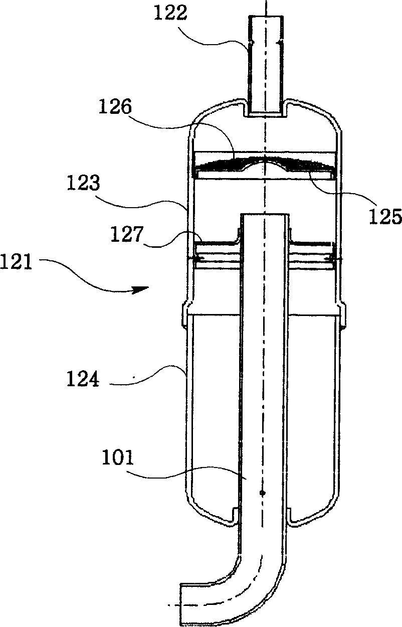
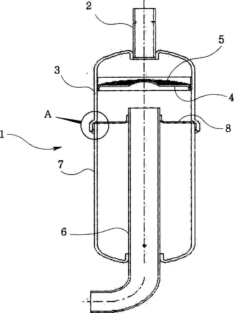
[0037] image 3 Shown is a longitudinal sectional view of the rotary compressor liquid storage tank according to the present invention, Figure 4 Shown is an enlarged cross-sectional view of the storage tank suction pipe holder according to the present invention, Figure 5 is to expand image 3 Sectional view of part A, Image 6 Illustrated is image 3 Longitudinal sectional view of another embodiment.

[0038] The liquid storage tank 1 of this rotary compressor is an upper cap 3 provided with a refrigerant inflow pipe 2 in the upper part; it is provided in the upper part o...


PUM


Abstract

This is a kind of liquid -storage tank of rotating type compressor. It includes upper cap, the upper side of which is set with refrigerants feeding pipe; and screen, which is set at the upper side of the inner side of upper cap and supported by screen support. It is used to separate refrigerant liquid; lower cap welding at the lower end part of the said upper cap; vertical part cutting through the lower part center of lower cap; L-flexible type feeding pipe connecting to compressor through horizontal part; feeding pipe fixer supporting the upper side of L-flexible type feeding type. It is between the upper cap and lower cap. They assembled together by welding so as to fixing more firmly in the liquid storage tank

Description

technical field [0001] The invention relates to a liquid storage tank connected to a rotary compressor, in particular to a holder for supporting a refrigerant suction pipe inside the liquid storage tank assembled between an upper cap and a lower cap in a firmer state. A liquid storage tank for a rotary compressor that improves productivity by improving the assembly process while eliminating the defect of noise caused by the sagging of the retainer. Background technique [0002] In general, a compressor is a device that transmits power from a power generating device such as an electric engine, and pressurizes a working fluid such as a refrigerant to increase the pressure of the working fluid. [0003] This type of compressor is widely used in the field of air conditioners, refrigerators and other general household appliances to the complete equipment industry. [0004] Such compressors are classified into positive displacement compressors and dynamic compressors or turbo com...

Claims


Application Information

Patent Timeline
IPC IPC(8): F04C29/00
Inventor 金锺穆
Owner LG ELECTRONICS (TIANJIN) APPLIANCES CO LTD
Why Eureka
Try Eureka