Continuously variable transmission

A technology of continuously variable transmissions and transmissions, applied in the direction of portable lifting devices, transmission parts, components with teeth, etc.

Inactive Publication Date: 2007-01-17
ROBERT BOSCH GMBH
View PDF1 Cites 2 Cited by
  • Summary
  • Abstract
  • Description
  • Claims
  • Application Information

AI Technical Summary

Problems solved by technology

However, known dry transmissions are not suitable, at least at present, for use in mid- and higher-class cars, for example cars with an engine torque of 125Nm or more

Method used


Image

  • Continuously variable transmission
  • Continuously variable transmission
  • Continuously variable transmission

Examples


Embodiment Construction

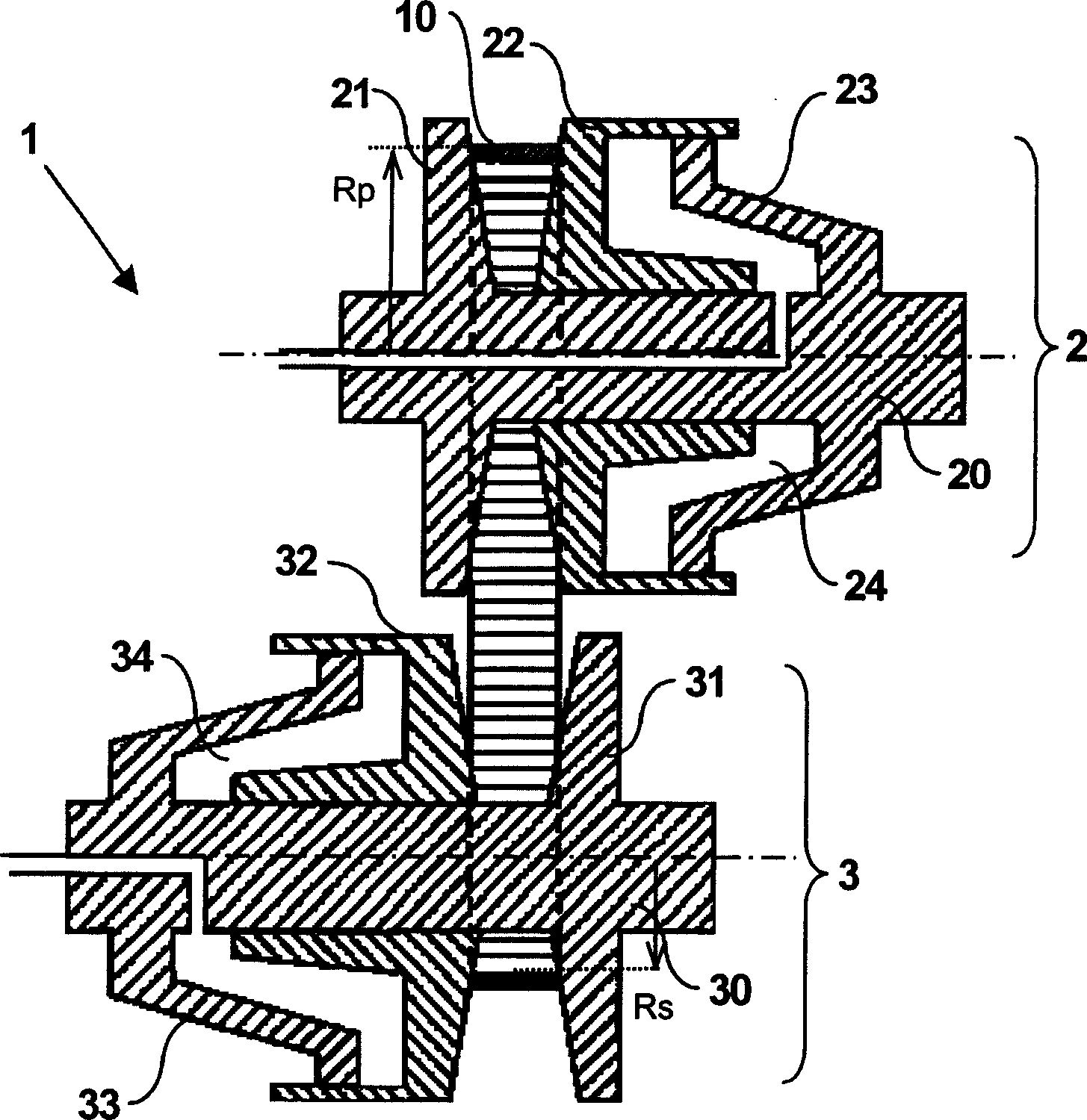
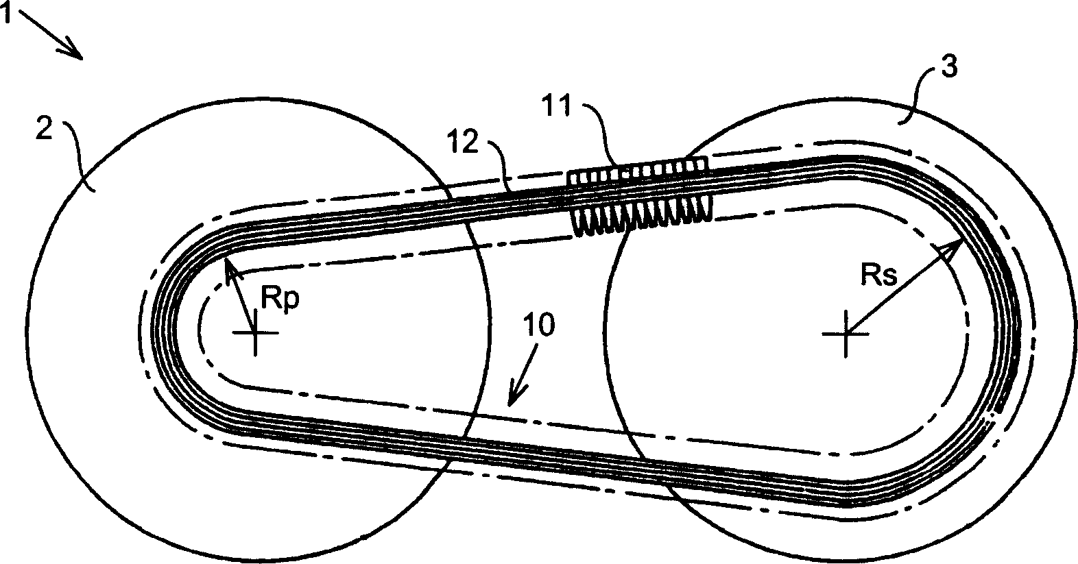
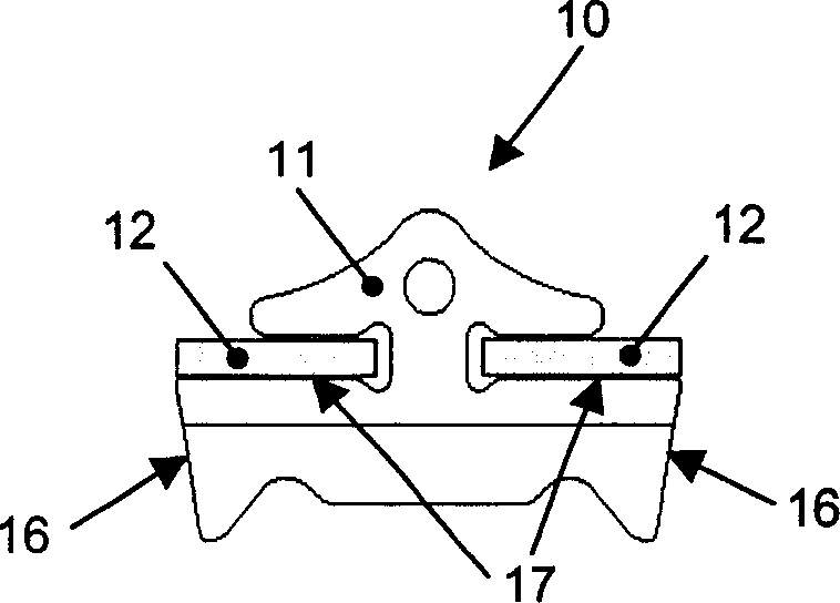
[0017] figure 1 A schematic illustration of a section through a continuously variable transmission according to the prior art is shown. A known transmission 1 includes a primary pulley 2 driveable by an engine (not shown) with a primary couple Tp and a secondary pulley 3 capable of driving a load (not shown) with a secondary couple Ts. The two pulleys 2 and 3 are provided with a pulley sheave 21, 31 fixedly fastened to the respective pulley shaft 20, 30 and the sheave 22, 32 can be moved axially relative to the shaft 20, 30 moves. The transmission element 10 , more specifically a push belt 10 , is clamped between the pulley pulleys 21 , 22 and 31 , 32 so that mechanical power can be transmitted between the two shafts 20 and 30 by means of friction. The axially oriented clamping force with which the transmission element 10 clamps each pulley 2 , 3 is implemented in this case by the drive. In this example, the drive means are formed by respective pressure chambers 24, 34 of t...


PUM


Abstract

A continuously variable transmission (1) has a pair of pulleys (2, 3), between which an endless transmission element (10), which is flexible in the longitudinal direction, is rotatably arranged, which pulleys (2, 3) and which transmission element (10) are at least largely made from metal, in which continuously variable transmission at least one of the contact surfaces in a frictional contact between the pulleys (2, 3) and the transmission element (10) is provided with an inorganic surface layer or coating, whereby the said frictional contact takes place without a continuous stream of a liquid lubricant being provided to it.

Description

technical field [0001] The invention relates to a continuously variable transmission as described in the preamble of claim 1 . A transmission of this type is generally known, for example from patent publication EP-A-1 167 829 in the applicant's name. The variator is designed with flexible variator elements formed from metal or at least metal parts so that relatively high powers can be transmitted, at least higher than that of commonly known optional reinforced plastic V-belts. Background technique [0002] Transmissions of this type based on metal transmission elements are very suitable and are therefore also widely used commercially in the drive of motor vehicles. However, one design drawback of these transmissions is the need for a virtually continuous flow of lubricant to the frictional contact between the transmission elements and the pulleys for cooling or to dissipate the frictional heat from the frictional contact. This configuration requires a high quality hydrauli...

Claims


Application Information

Patent Timeline
IPC IPC(8): F16H55/56F16H57/05
CPCF16H55/56F16H57/05
Inventor 马克·范德勒根阿尔耶恩·布兰茨玛沃尔克·哈斯
Owner ROBERT BOSCH GMBH
Why Eureka
Try Eureka