Contact holding structure of connector

A technology for maintaining structures and connectors, applied in the direction of connection, components of connection devices, fixed/insulated contact components, etc., can solve problems such as falling off, and achieve the effect of simple structure, no increase in the number of devices, and easy assembly and disassembly

Inactive Publication Date: 2007-01-17
JAPAN AVIATION ELECTRONICS IND LTD
View PDF0 Cites 8 Cited by
  • Summary
  • Abstract
  • Description
  • Claims
  • Application Information

AI Technical Summary

Problems solved by technology

Moreover, since each contact 43 is inserted into each through-hole 42a of the insulator 42 by a met

Method used


Image

  • Contact holding structure of connector
  • Contact holding structure of connector
  • Contact holding structure of connector

Examples


Embodiment 1

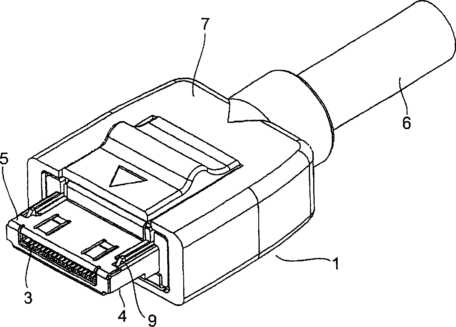
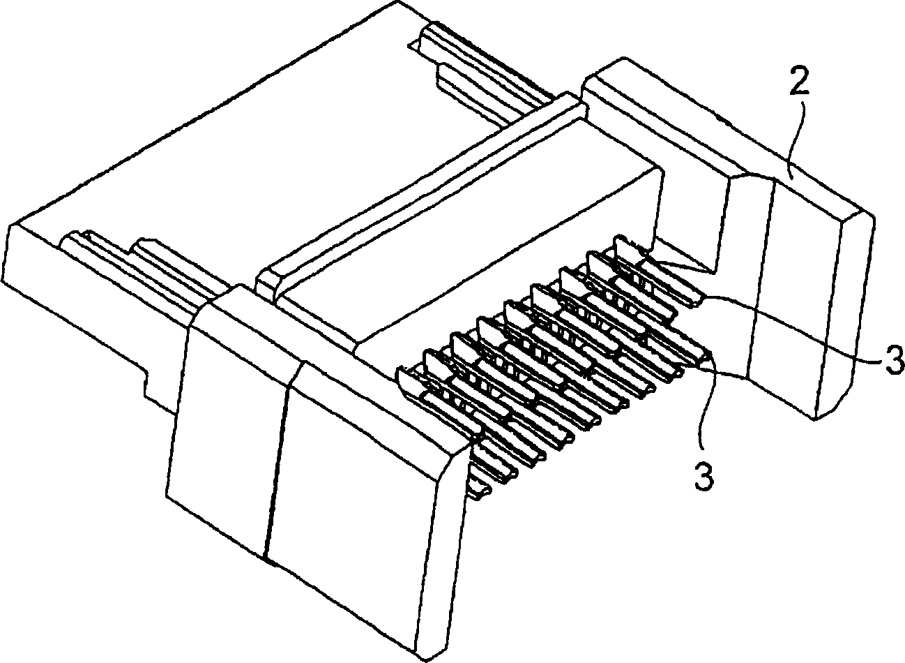
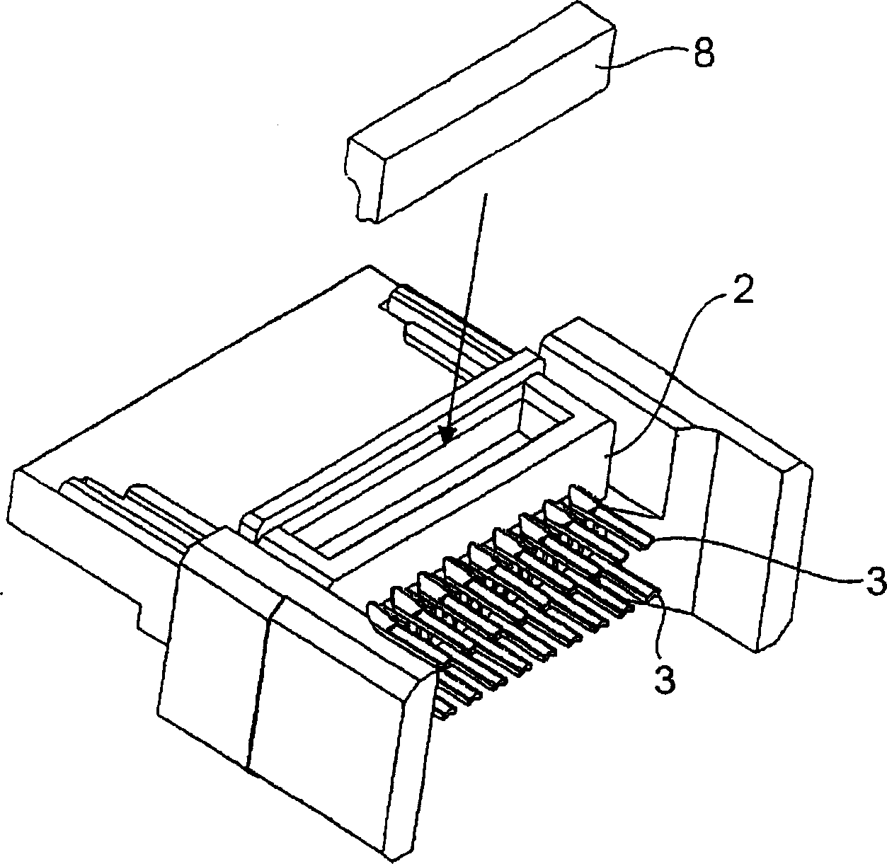
[0041] refer to Figure 1 to Figure 6 , to illustrate the plug connector of Embodiment 1 of the present invention. figure 1 is a perspective view viewed from the front side of the plug connector, figure 2 It is a perspective view viewed from the rear side of the plug connector before attaching a hood, etc., image 3 It is a perspective view viewed from the back side of the plug connector before the retainer (the member that fixes the contacts in the insulator) is installed in the insulator, Figure 4 is a perspective view viewed from the rear side of the plug connector with the retainer installed in the insulator, Figure 5 is a sectional view showing the state before the contact is installed in the insulator, Figure 6 The upper side of shows the cross-sectional view when the contact is installed deeply in the insulator, Figure 6 The lower side of the shows a cross-sectional view of the contact installed shallowly in the insulator.

[0042] First, refer to Figure 1 ...

Embodiment 2

[0051] refer to Figure 7 , to illustrate the second embodiment of the present invention. In the first embodiment, the contacts 3 are arranged in one row. On the other hand, in the second embodiment, the contacts 3 are arranged so as to face each other in two rows of upper and lower layers, and the holders 8 are inserted into the insulator 2 from the upper and lower directions.


PUM


Abstract

A simply formed and rigid contact holding structure of a connector in which the positions of the contact parts of a plurality of contacts are different from each other. When the contact (3) is deeply fitted into an insulator (2), first the contact is inserted into a contact storage part (2a) in the direction of an arrow in step 1. Next, a holder (8) is inserted into a holder storage part (2b) in the direction of an arrow in step 2, and an engagement part (8a) is engaged with a latch (engaged part) (3d2). Then, the contact is fixed to the insulator. When the contact is shallowly fitted into the insulator, the engagement part is engaged with the latch (3d1). As a result, a position difference is formed in the fitting direction of the connector between the contact part (3a) of the contact in the first case and the contact part of the contact in the second case.

Description

technical field [0001] The present invention relates to a structure for holding contacts in an insulator in a connector, and more specifically, relates to a connection in which a plurality of identical contacts are firmly held in an insulator and the position of the contacts in the insulator can be changed device. Background technique [0002] refer to Figure 8 ~ Figure 10 , the contact holding structure of the first conventional connector will be described. [0003] First, the plug connector 21 will be described. The contact 23 consists of a protruding contact portion 23a, a spring portion 23b, a holding portion (press-fit portion) 23c held in the insulator 22, and a connection portion 23d to which an electric wire of a cable (not shown) is soldered in order from the front end. constituted in a continuous manner. Two engagement protrusions 23c1 and 23c2 are formed on the holding portion 23c. [0004] The insulator 22 is provided with a contact accommodating portion 22a...

Claims


Application Information

Patent Timeline
IPC IPC(8): H01R13/42H01R24/00H01R13/436
CPCH01R13/4361H01R23/02H01R2107/00H01R24/60H01R13/436H01R13/42
Inventor 村山龙介
Owner JAPAN AVIATION ELECTRONICS IND LTD
Why Eureka
Try Eureka