Burner with air balancing device

A burner and equalization technology, applied to gas fuel burners, burners, combustion methods, etc., can solve the problems of gas reactive power loss, affecting gas combustion efficiency, etc., and achieve the effect of improving combustion thermal efficiency

Inactive Publication Date: 2007-01-24
佛山市顺德区澳羚究星电子科技有限公司
View PDF1 Cites 17 Cited by
  • Summary
  • Abstract
  • Description
  • Claims
  • Application Information

AI Technical Summary

Problems solved by technology

[0002] At present, in the gas appliance industry, especially in the civil gas appliance industry, with the intensification of market competition, various manufacturers continue to develop stoves with various specifications and wide adaptability on the basis of the original design. In general, it basically revolves around the two main lines of improving thermal efficiency and energy saving. Its core is to solve the problem of the mixing ratio of gas and air in gas preparation. The patent No. ZL02134478.7 declared by the inventor in 2002 is an energy-saving gas combustion In view of the above existing problems, structural improvements have been made, and the internal and external gas chambers are organically connected into a structure that is separated from each other and communicated with each other through an air channel, which improves the preparation of gas to a certain extent. On the basis of the improved combustion rate of gas, a certain amount of gas is saved, but this technical solution also has the disadvantages shared by existing gas appliances, that is, there is still a vacuum area in the central area of ​​the fire cover when the gas is burning. Because there is more gas and less air in one area, it not only affects the efficiency of gas combustion, but also causes reactive power loss of gas

Method used


Image

  • Burner with air balancing device
  • Burner with air balancing device
  • Burner with air balancing device

Examples


Embodiment Construction

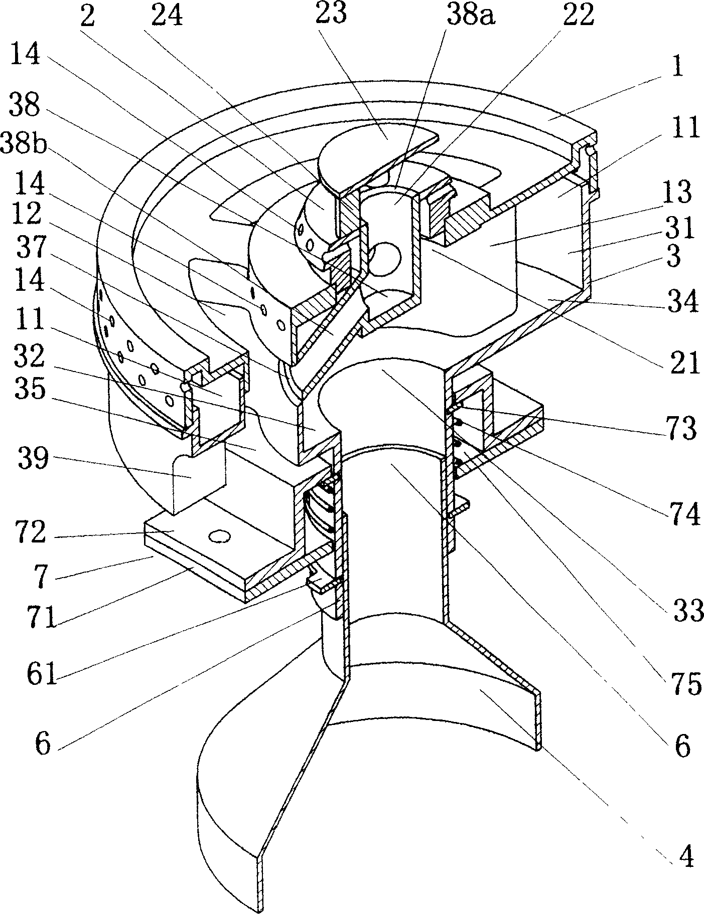
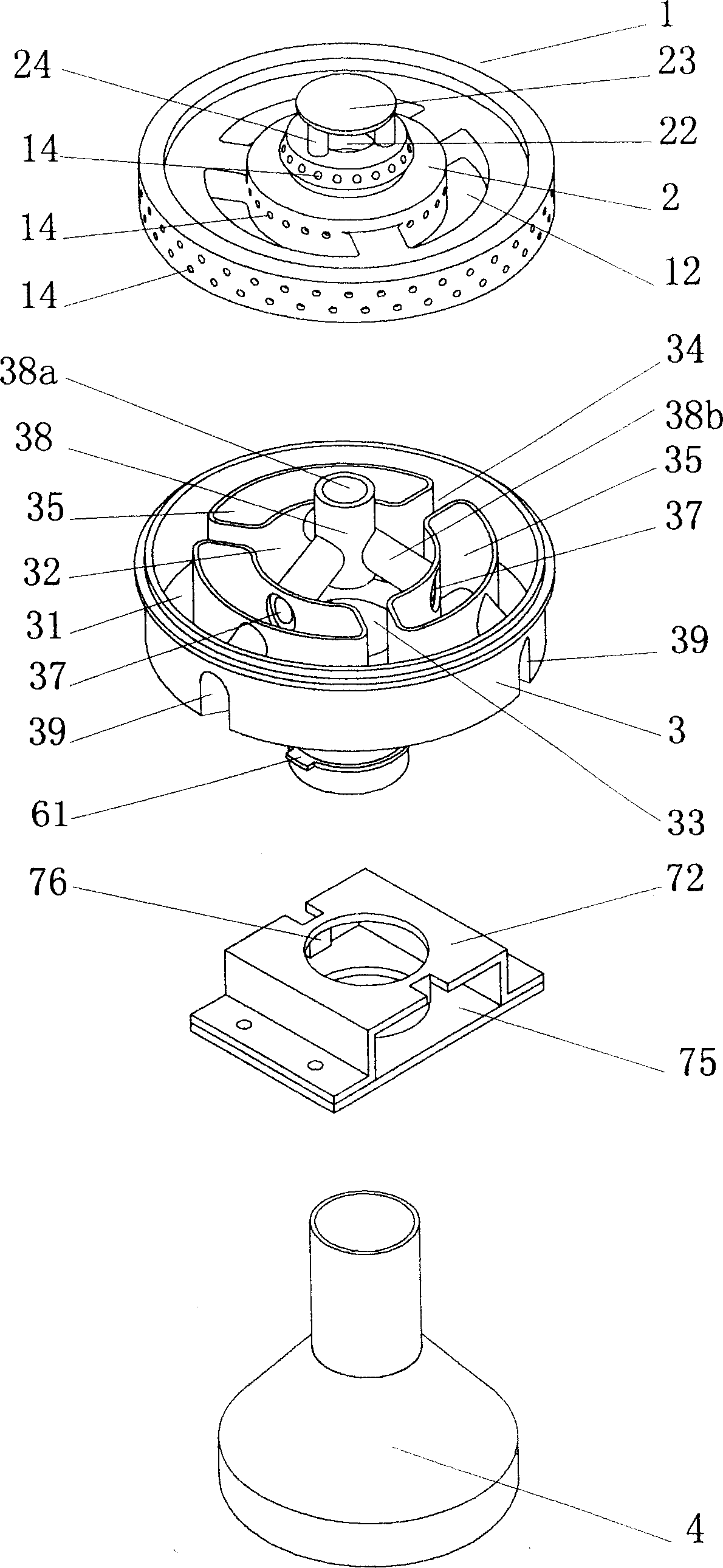
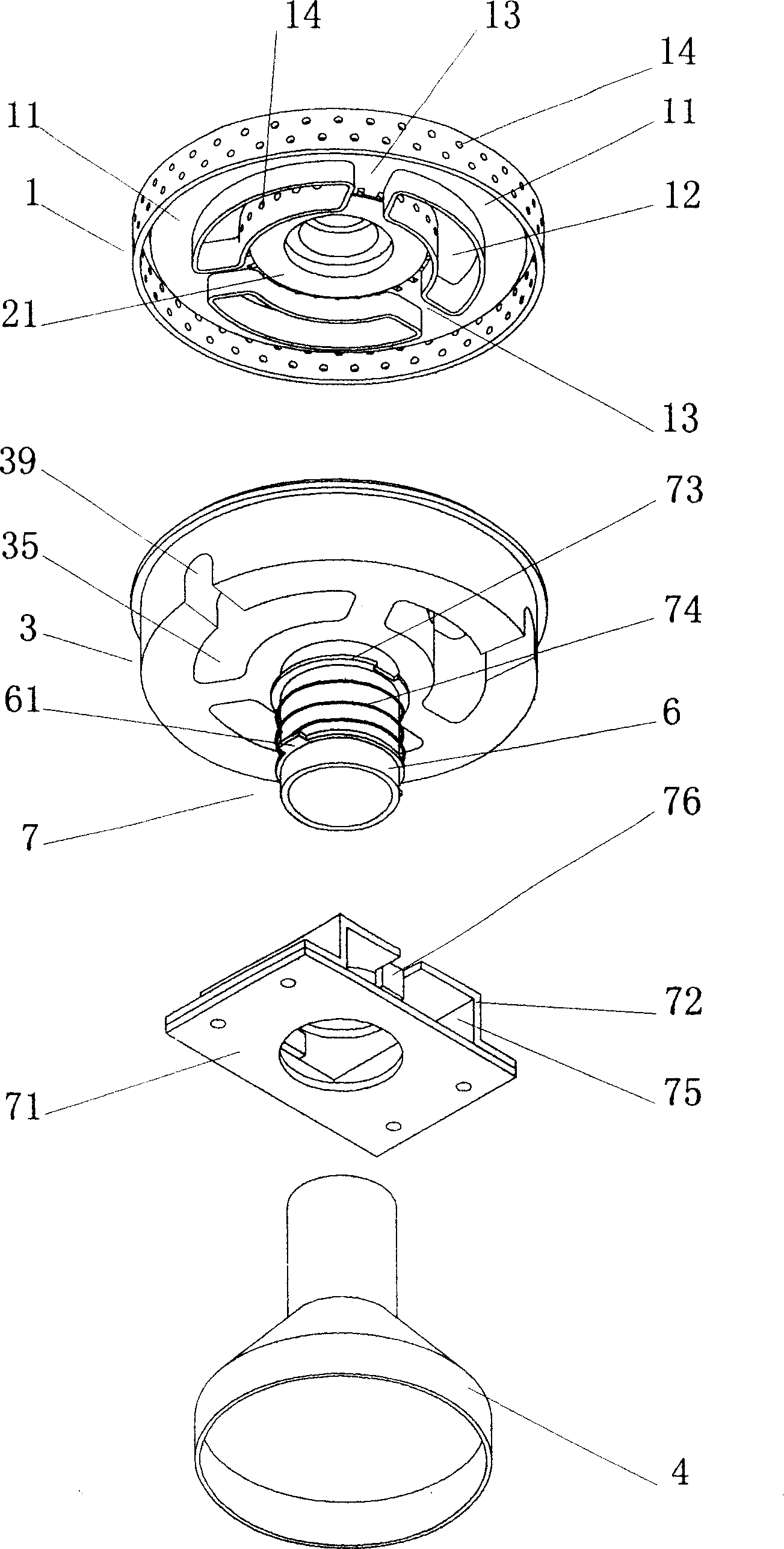
[0015] The present invention as figure 1 , figure 2 , image 3 As shown, a burner with balanced gas distribution includes a gas seat 3 with an air mixing pipe 4 at the bottom, an inner fire cover 2 and an outer fire cover 1 arranged above the gas seat 3, and the seat of the gas seat 3 The cavity is provided with an outer ring gas groove 31 facing the outer gas chamber 11 of the outer fire cover 1 and an inner ring gas groove 32 facing the inner gas chamber 21 of the inner fire cover 2. The bottom of the inner ring gas groove 32 is provided with a gas inlet 33 , between the inner ring gas groove 32 and the outer ring gas groove 31, there are several communicating gas passages 34, and between two adjacent gas passages 34, there are several outer air mixing passages 35 separated from the gas passage 34, It is characterized in that an inner air mixing channel is provided between each of the outer air mixing channels 35 and the inner fire cover 2, wherein:

[0016] Above-mentio...


PUM


Abstract

Burner with balanced air distribution includes fuel gas seat with pipe of mixing wind being installed on base, and inner fire cover and outer fire cover setup above the fuel gas seat. Outer and inner annular air grooves are setup in seat cavity of the fuel gas seat. Fuel gas channel is setup between outer and inner annular air grooves. There are outer air mixing channels between two adjacent fuel channels, and isolated from fuel gas channels. Inner air mixing channels are setup between outer air mixing channel and inner fire cover. Inner air mixing channels make air possible to enter to central area of the inner fire cover from outer air mixing channels. Thus, the invention overcomes disadvantages of deficient burning caused by not even mixing ratio between fuel gas and air in inner fire cover of traditional burner. Interconnected structure designed for structure of inner and outer air mixing channels is more in favor of balanced matching so as to raise thermal efficiency.

Description

technical field [0001] The invention relates to a gas appliance, in particular to a burner with gas distribution balance. Background technique [0002] At present, in the gas appliance industry, especially in the civil gas appliance industry, with the intensification of market competition, various manufacturers continue to develop stoves with various specifications and wide adaptability on the basis of the original design. In general, it basically revolves around the two main lines of improving thermal efficiency and energy saving. Its core is to solve the problem of the mixing ratio of gas and air in gas preparation. The patent No. ZL02134478.7 declared by the inventor in 2002 is an energy-saving gas combustion In view of the above existing problems, structural improvements have been made, and the internal and external gas chambers are organically connected into a structure that is separated from each other and communicated with each other through an air channel, which impr...

Claims


Application Information

Patent Timeline
Patent Type & Authority Applications(China)
IPC IPC(8): F23D14/34F23D14/62F23D14/48F24C3/08
Inventor 胡志学
Owner 佛山市顺德区澳羚究星电子科技有限公司
Why Eureka
Try Eureka