Boiler using gas or fuel oil

An oil-fired boiler and gas technology, applied in the field of combustion equipment boilers, can solve the problems of low boiler thermal efficiency and high nitrogen oxides, and achieve the effect of avoiding excessively high volume heat load

Inactive Publication Date: 2006-11-15
UNIV OF SCI & TECH OF CHINA
View PDF0 Cites 10 Cited by
  • Summary
  • Abstract
  • Description
  • Claims
  • Application Information

AI Technical Summary

Problems solved by technology

[0004] The invention provides a gas-fired or oil-fired boiler to realize flameless combustion and overcome the defects of high temperature zone, high emission of atmospheric pollutants, especially nitrogen oxides, and low thermal efficiency of the boiler in the existing boiler combustion process

Method used


Image

  • Boiler using gas or fuel oil
  • Boiler using gas or fuel oil

Examples


Embodiment 1

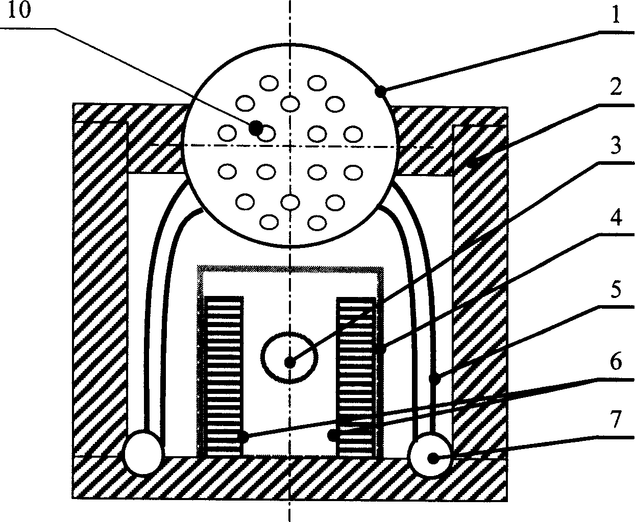
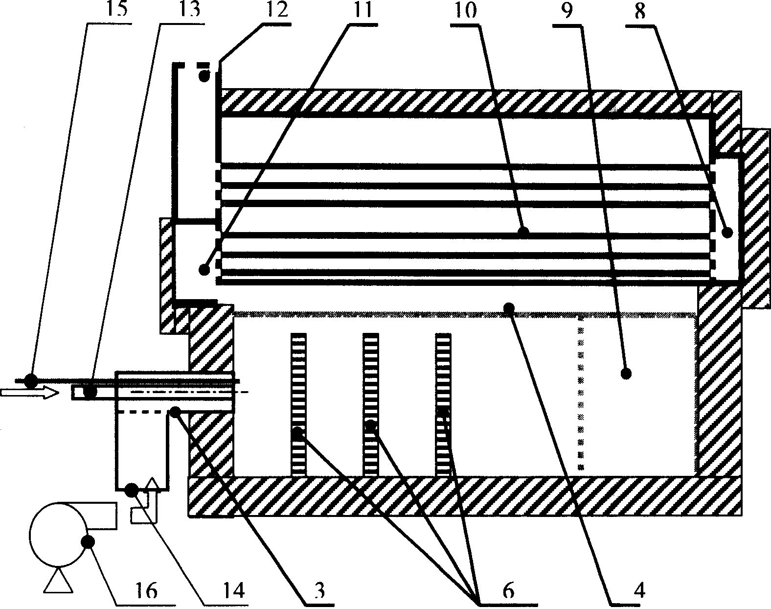
[0015] In this embodiment, refractory materials are laid on the bottom of the boiler body, surrounded by refractory furnace walls 2; a cylindrical drum 1 is erected above the boiler body, and the upper half of the drum is provided with a main steam valve, an auxiliary steam valve, a safety valve, and a safety valve respectively connected by pipelines. Valve, water level gauge and pressure gauge, the upper half of the outer front end of the drum is connected with the flue gas outlet 12, the lower half is connected with the front smoke box 11, the rear end is connected with the rear smoke box 8, and the inside of the drum is along the axis direction Arrange the upper and lower groups of smoke pipes 10, the lower set of smoke pipes 10 are respectively connected to the front smoke box 11 and the rear smoke box 8, and the upper set of smoke pipes are respectively connected to the rear smoke box 8 and the smoke outlet 12; A drain pipe is led out obliquely downward on both sides respe...

Embodiment 2

[0021] In this embodiment, a traditional coal-fired boiler is transformed, and a combustion stirring reactor is installed in the furnace, and the fuel air supply device is designed according to the furnace load, so that it becomes a boiler of the present invention capable of burning gas or liquid fuel.

[0022] The structure of the traditional coal-fired boiler used is: the boiler body is surrounded by a refractory furnace wall 2, the upper drum 1 is erected above, and the smoke pipe is arranged inside the upper drum 1, and the upper half of the upper drum 1 is respectively connected to the steam boiler by pipes. Valves, safety valves, water level gauges and pressure gauges extend downward from the lower half of the upper drum 1 to connect to the lower drum, where a part of the water pipes are attached to or embedded in the furnace wall 2 to form a radiant heating surface—— The water-cooled wall, the lower drum is placed at the bottom of the boiler, and a sewage valve is installe...

Embodiment 3

[0026] In this embodiment, three pieces (6 pieces in total) of regenerators 6 are separately placed on the bottom of the combustion stirring reactor against the two side walls of the combustion chamber. The shape is cuboid, the height of each regenerator accounts for 80% of the combustion chamber height, the length accounts for 8% of the combustion chamber length, and the width accounts for 10% of the combustion chamber width; after setting the regenerator in the combustion stirring reactor, due to It assists the wall of the hot combustion stirred reactor to conduct a strong heat exchange with the mixed gas, so the temperature distribution is more uniform, and it helps the stirring and mixing of the gas inside the combustion stirred reactor.

[0027] Other parts are identical with embodiment 1 or 2.


PUM


Abstract

There is disclosed a gas-firing or oil-burning boiler, in which, a combustion stirring reactor and a combustion chamber connected with a liquid or gaseous fuel feeding device are mounted in the hearth. The hearth bed is used as the boiler bed and the side wall of the hearth is connected with the boiler bed. The surface of the hearth side wall is made of materials capable of resisting the temperature not below 1500 deg. c. The fuel feeding device is connected with the combustion chamber through the front boiler wall and at the exhaust nozzle is disposed an igniter. When the temp. on the wall surface of the combustion chamber is not below 850 deg. c. the boiler can realize non-flame burning in the boiler.

Description

Technical field: [0001] The invention belongs to the technical field of combustion equipment boilers, in particular to flameless combustion gas and oil boilers. Background technique: [0002] "Boiler Principles and Calculation" (Edited by Feng Junkai and Shen Youting, Science Press, 1992) pp. 60-64 introduces the principle of boiler combustion gas, points out that the outlet of the fuel air supply device will form a flame tongue or torch, and the length of the torch is calculated calculate. "Structure Design and Atlas of Fuel Gas Boiler" (edited by Zhao Qinxin, Li Weidong, Hui Shien, Luo Zhenghui, Xi'an Jiaotong University Press, 2002), pages 125-143, introduces modern fixed industrial water tube steam boilers (including D type, A type, O-type and corner tube boilers) internal structure and working method, which is based on the structure of drum, header, water pipe, furnace, the fuel air supply device is directly connected to the furnace, and the flame is ejected from the o...

Claims


Application Information

Patent Timeline
Patent Type & Authority Applications(China)
IPC IPC(8): F23C1/08F23C3/00F23C5/32
Inventor 林其钊邢献军李业发
Owner UNIV OF SCI & TECH OF CHINA
Why Eureka
Try Eureka