Method and its device for high speed winding metal wire on core wire

A metal wire and core wire technology, applied in coil manufacturing, transportation and packaging, transportation of filamentous materials, etc., can solve the problems of low production efficiency and low winding speed, and achieve improved production efficiency, uniform winding pitch, Easy to debug effects

Inactive Publication Date: 2007-01-24
钱潜
View PDF0 Cites 2 Cited by
  • Summary
  • Abstract
  • Description
  • Claims
  • Application Information

AI Technical Summary

Problems solved by technology

[0003] The purpose of the present invention is to solve the problem of low production efficiency due to the low winding speed of existing metal wires, and to provide a method and device for winding metal wires at high speed by using centrifugal force to pay off wires

Method used


Image

  • Method and its device for high speed winding metal wire on core wire
  • Method and its device for high speed winding metal wire on core wire
  • Method and its device for high speed winding metal wire on core wire

Examples


Embodiment Construction

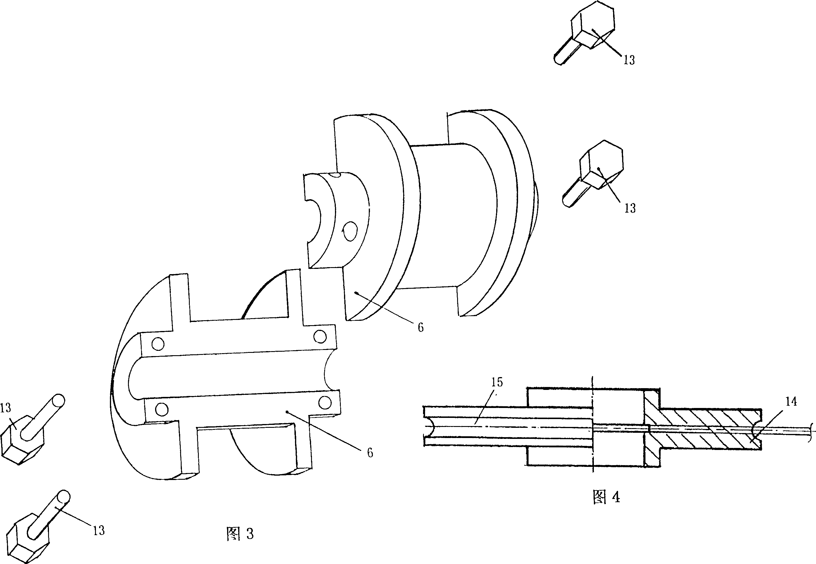
[0024] The following structural drawings and embodiments further illustrate the present invention.

[0025] Such as figure 1 ~4 shown.

[0026] A method for winding a metal wire at a high speed on a core wire, comprising the following steps:

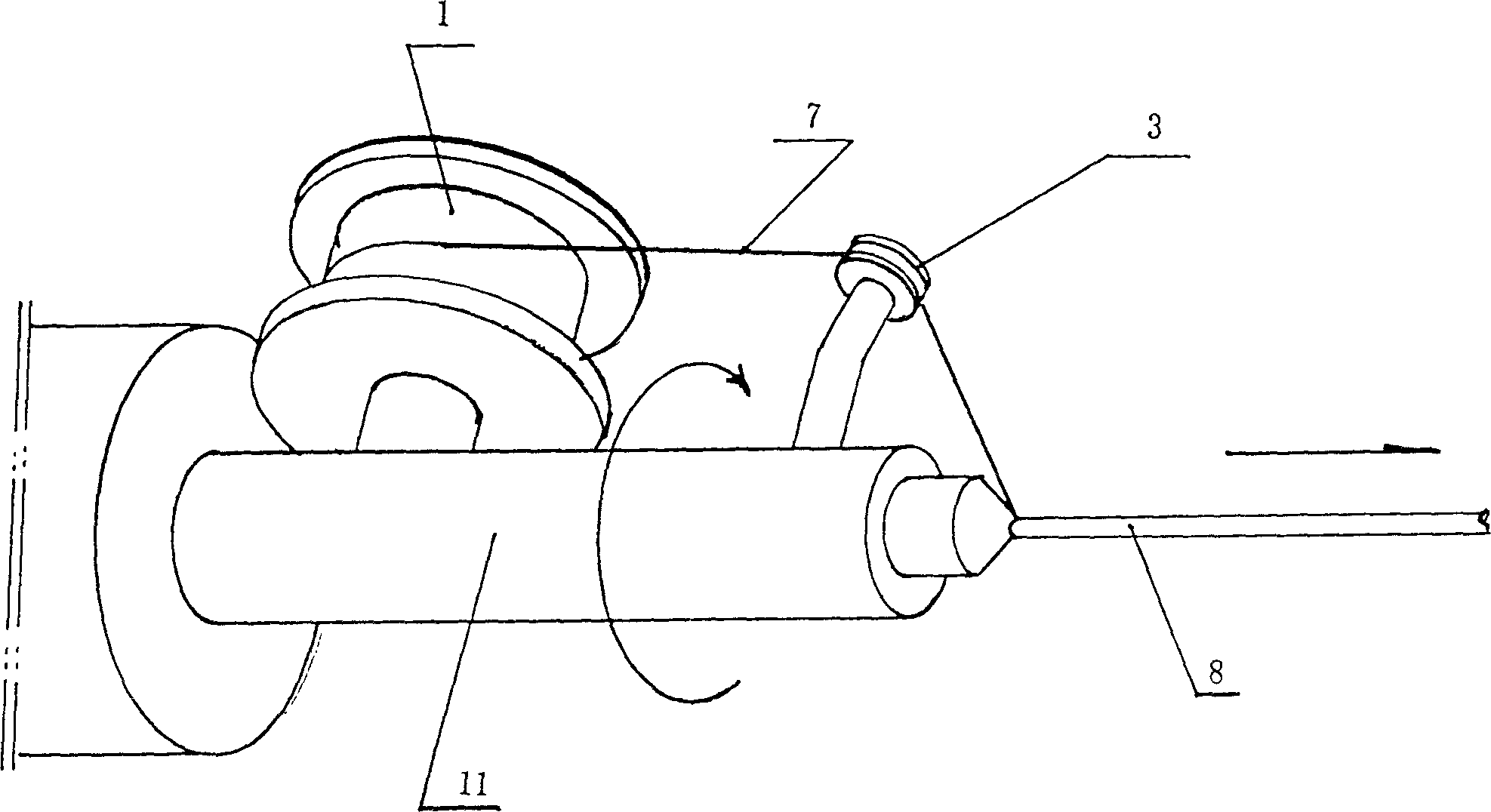
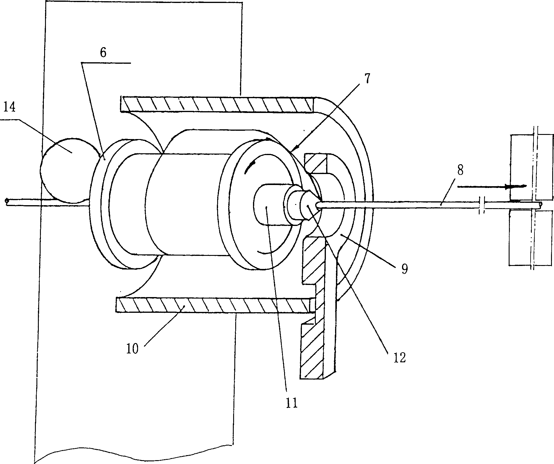
[0027] a. Turn the core wire through the rotating shaft, and install the guide wire nozzle on the same end of the rotating shaft as the core wire advances;

[0028] b. Connect the outer coil wound with the metal wire to the rotating shaft, and lead the metal wire to the core wire at the guide wire along the tangential direction opposite to the rotation direction of the rotating shaft and fix it;

[0029] c. Install a throwing cylinder on the outer side of the outer winding reel to prevent the metal wire from being away from the outer winding reel under the action of centrifugal force, so that the metal wire is in the throwing cylinder, and at the same time install a wire at the position of the guide wire nozzle to prevent the metal wir...


PUM


Abstract

This invention provides a method and a device for utilizing centrifugal force to pay off metal wires for winding metal wires quickly including a shaft, a core wire passing through the shaft, a wire leading nozzle mounted on a same end of the shaft to the outlet end, an outer winding disk fixed on the shaft and rotating synchronously with it, a wire-thrower cover mounted at the outside of the outer-winding disk, a blocking coil mounted on an end of the thrower near the leading nozzle, in which, the core wire passes through the blocking coil, the pay-out end of the wire is led out from the tangent direction on the outer winding disk opposite to the rotation direction of the shaft and fixed on the core wire in the blocking coil.

Description

technical field [0001] The invention relates to a method and equipment for winding metal wires such as damping wires (wires), ignition coil wires (wires), and resistance wires (wires) on core wires when making electrical components. A method and device for winding metal wires on-line at high speed. Background technique [0002] At present, in the manufacturing process of damping wires, ignition coils, resistance wires and other products, one of the bottlenecks is to uniformly wind a metal wire (usually an alloy wire, the same below) on a core wire. Due to the diameter of the wire Thin (usually 0.04 ~ 0.2mm), easy to break or uneven pitch during winding. Therefore, the traditional winding method (such as figure 1 As shown), the winding speed is limited to about 2000 rpm, and the production efficiency is too low. Contents of the invention [0003] The object of the present invention is to solve the problem of low production efficiency due to the low winding speed of exist...

Claims


Application Information

Patent Timeline
Patent Type & Authority Applications(China)
IPC IPC(8): H01F41/06H01B17/00H01B3/00B65H54/00H01F41/096
Inventor 钱浩韩国建钱潜
Owner 钱潜
Why Eureka
Try Eureka