Evaporation system

A technology of evaporation equipment and evaporator, which is applied in the directions of evaporation, total evaporation, multi-effect evaporation, etc., and can solve the problem of the limitation of the number of evaporator stages in series.

Active Publication Date: 2007-01-24
GEA WIEGAND
View PDF0 Cites 6 Cited by
  • Summary
  • Abstract
  • Description
  • Claims
  • Application Information

AI Technical Summary

Problems solved by technology

Because the temperature increase of residual vapor is relatively small, the number of evaporator stages connected in series is greatly limited in traditional multi-stage evaporation equipment using residual vapor compression

Method used


Image

  • Evaporation system

Examples


Embodiment Construction

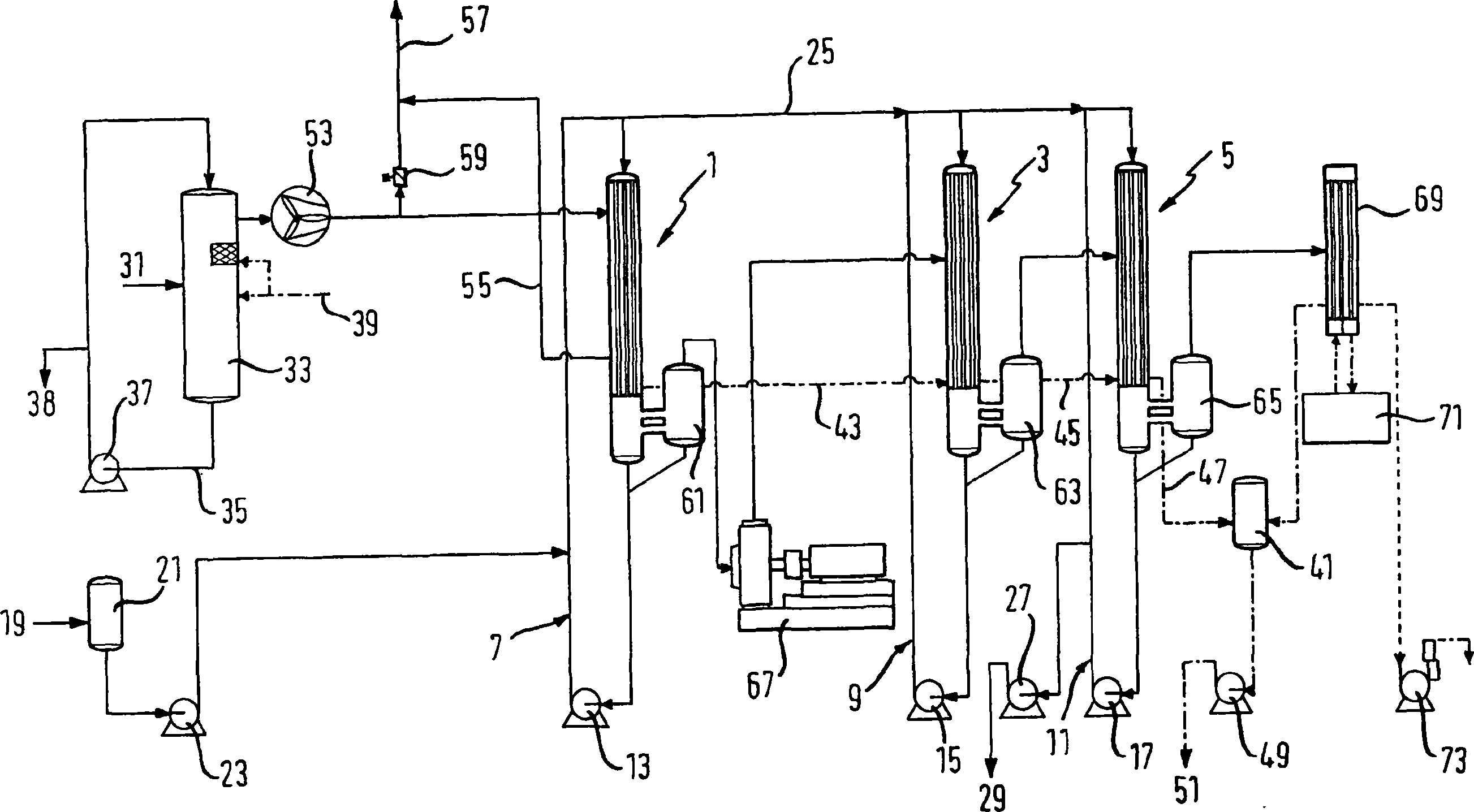
[0010] The evaporation plant comprises three evaporator stages 1 , 3 , 5 each formed as a down-flow evaporator, each evaporator stage comprising a product circulation circuit 7 , 9 or 11 with a circulation pump 13 , 15 or 17 . The product to be evaporated, supplied at 19 via a buffer container 21 and a delivery pump 21, is fed into the circulation circuit 7 of the first evaporator stage 1 and is usually supplied via this circulation circuit 7 to the evaporator chamber of the evaporator stage 1 in the upper area. In the same way, the product to be evaporated also reaches the circulation loop 9 , 11 of the evaporator stages 3 , 5 via the line 25 . The evaporated concentrate is discharged at outlet 29 by means of delivery pump 27 .

[0011] The heating energy required to heat the evaporator stages 1, 3 and 5 uses the superheated steam-air-mixture from a dryer stage not shown in detail, which mixture is fed at 31 to a spray-wet-scrub column 33, This washing column removes dust e...


PUM


Abstract

The invention relates to a multi-step evaporation system whereby the first evaporator (1) is heated by means of a jet-wet-washer (33) with overheated vapour containing air, e.g. of a drier. The product vapour of the first evaporation step (1) is guided to a second evaporation step (3) for heating by means of a mechanical compressor (67). The compressor (67) reduces the saturation temperature in the evaporation chamber of the first evaporation step (1) and increases the temperature of the product vapour guided to the second evaporation step (3) for heating.

Description

technical field [0001] The invention relates to an evaporation plant comprising an evaporator heated by process waste steam and a process stage heated by product vapor of the evaporator, in particular at least one further evaporator. Background technique [0002] In order to operate the evaporation plant as economically as possible, the heating of the evaporator, for example, uses additional process heat that occurs, for example in the form of waste steam generated in the process. However, such process waste steam, produced for example as waste steam of the dryer stage, can only be used to a limited extent since it is produced at relatively low pressure or mixed with air or inert gases. The condensing capacity of evaporators heated with such process waste steam is generally reduced and the number of evaporator stages heated with such process waste steam and thus the efficiency of the evaporation plant is significantly limited. [0003] In multi-stage evaporation plants, it ...

Claims


Application Information

Patent Timeline
Patent Type & Authority Applications(China)
IPC IPC(8): B01D1/28B01D1/26
CPCB01D1/2846Y10S159/08Y10S203/08Y10S203/11B01D1/26
Inventor H·普拉沙克
Owner GEA WIEGAND
Why Eureka
Try Eureka