
Liquid ejection apparatus and drive method for inkjet head

A technology of inkjet printing head and jetting device, which is applied in the direction of printing device, printing, etc., can solve problems such as damage to piezoelectric elements, and achieve the effect of preventing deterioration

Inactive Publication Date: 2013-07-31
FUJIFILM CORP +1
View PDF9 Cites 4 Cited by
  • Summary
  • Abstract
  • Description
  • Claims
  • Application Information

AI Technical Summary

Problems solved by technology

Furthermore, if the atmosphere surrounding the piezoelectric element is high in humidity before starting to supply dry air, there is a problem that damage to the piezoelectric element will be caused at the moment when voltage is applied to the piezoelectric element

Method used


Image

  • Liquid ejection apparatus and drive method for inkjet head
  • Liquid ejection apparatus and drive method for inkjet head
  • Liquid ejection apparatus and drive method for inkjet head

Examples


Embodiment Construction

[0065]

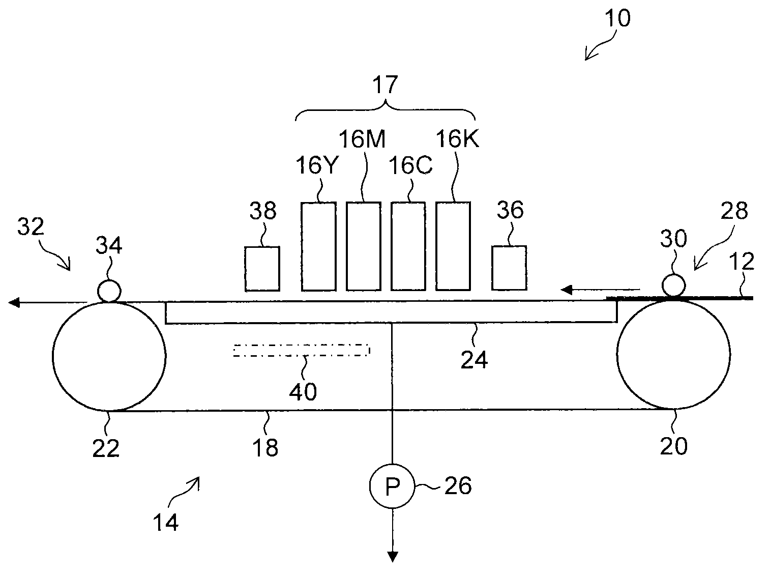
[0066] figure 1 is a schematic diagram of an inkjet recording apparatus 10 according to an embodiment of the present invention. The inkjet recording apparatus 10 is a drop-on-demand inkjet recording apparatus, and includes a recording medium transport unit 14 configured to hold and transport a recording medium 12, a printing unit 17 including inkjet print heads 16K, 16C, 16M, and 16Y , the inkjet printhead is configured to eject and deposit color ink droplets corresponding to black (K), cyan (C), magenta (M) and yellow (Y) onto the recording medium held in the recording medium transport unit 14. on medium 12.

[0067] The recording medium conveying unit 14 includes: an endless conveying belt 18 having a plurality of suction holes (not shown) in a recording medium holding area holding the recording medium 12; On the roller 20 and the idler roller column 22; the cavity 24 is arranged on the back side of the conveyor belt 18 in the recording medium holding area (on t...


PUM


Abstract

A liquid ejection apparatus includes: a gas chamber surrounding a piezoelectric element in an inkjet head; and a dry gas supply device configured to start supply of dry gas to the gas chamber before supply of electric power to the inkjet head is started, to continue the supply of the dry gas while the supply of the electric power to the inkjet head is continued, and to halt the supply of the dry gas after the supply of the electric power to the inkjet head is halted. While the dry gas supply device halts the supply of the dry gas to the gas chamber, a dry gas supply flow channel opening and closing device is closed to disconnect the dry gas supply device and the gas chamber, and a gas return flow channel opening and closing device is closed to disconnect the gas chamber and the external air.

Description

technical field [0001] The present invention relates to a liquid ejecting device and a driving method of an inkjet printhead, and more particularly to a driving technique for a piezoelectric device arranged in the inkjet printhead. Background technique [0002] As a driving method for an inkjet print head used in an inkjet recording apparatus, known are a piezoelectric method and a thermal method. In the piezoelectric method, ink is ejected from a nozzle by utilizing mechanical deformation of a piezoelectric device. In the thermal method, ink is ejected from a nozzle by utilizing a film boiling effect of ink stored in a liquid chamber connected to the nozzle. The piezoelectric method has the advantage over the thermal method that it is easier to control the ink ejection amount and ejection speed. [0003] A piezoelectric device for an inkjet printhead needs to be composed of a piezoelectric element made of a material having a piezoelectric coefficient (electrical-mechanica...

Claims


Application Information

Patent Timeline
Patent Type & Authority Applications(China)
IPC IPC(8): B41J2/01B41J29/377
CPCB41J2/175B41J29/12B41J2/195B41J2/14233B41J29/377B41J29/38
Inventor 柴田博司若林彰片冈雅树来嘉平柚木浩介
Owner FUJIFILM CORP
Learn More